Liquid crystal display device

a display device and liquid crystal technology, applied in lighting and heating devices, grass drying, instruments, etc., can solve the problems of degrading display quality, changing light luminance, and generating light leakage due to friction force, etc., to achieve the effect of improving display quality

Active Publication Date: 2005-11-17
LG DISPLAY CO LTD
View PDF4 Cites 7 Cited by
  • Summary
  • Abstract
  • Description
  • Claims
  • Application Information

AI Technical Summary

Benefits of technology

[0016] An object of the present invention is to provide a liquid crystal display device that improves a display quality.

Problems solved by technology

The friction force causes an abnormal variation of liquid crystal arrangement, and thus a light luminance is changed.
In particular, when the LCD device is operated in a Normally Black Mode, a light leakage can be generated due to the friction force.
Therefore, display quality can be degraded.

Method used


Image

  • Liquid crystal display device
  • Liquid crystal display device
  • Liquid crystal display device

Examples


Embodiment Construction

[0032] Reference will now be made in detail to the illustrated embodiments of the present invention, which are illustrated in the accompanying drawings.

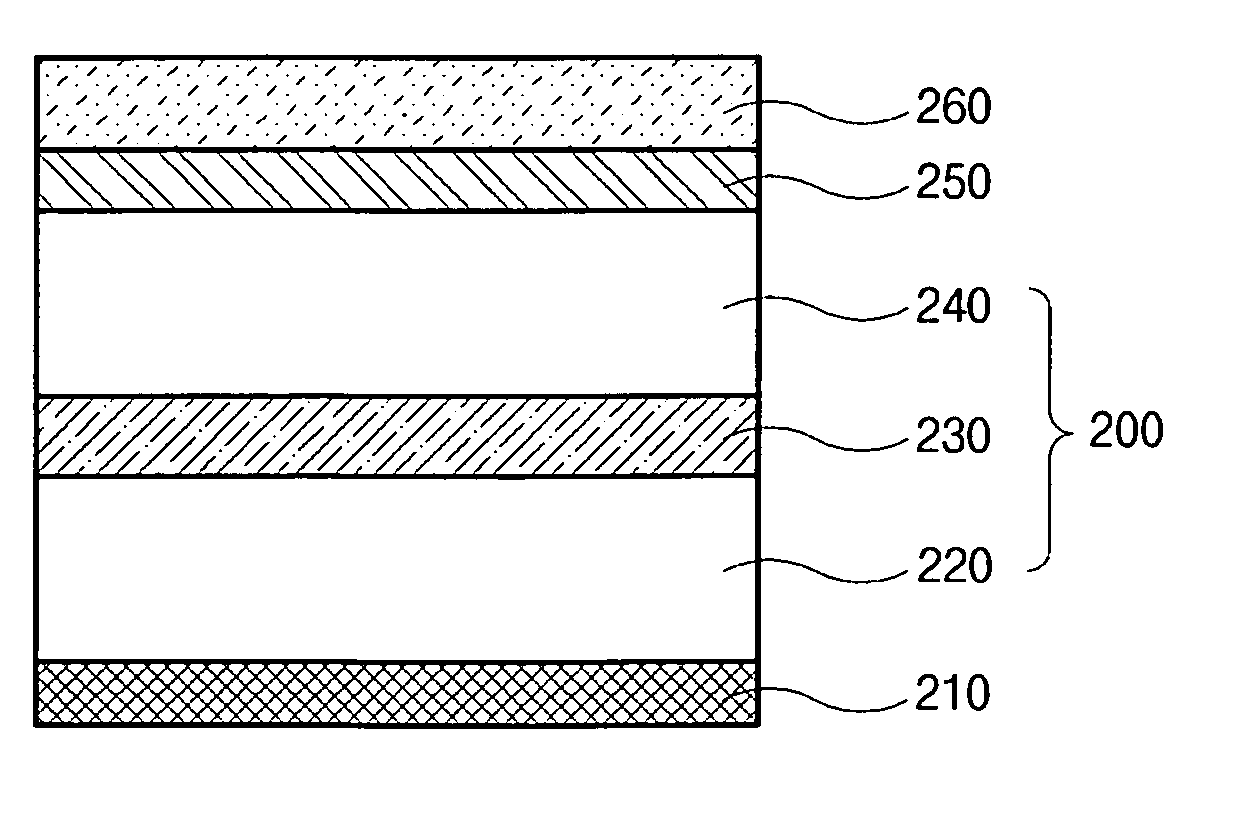
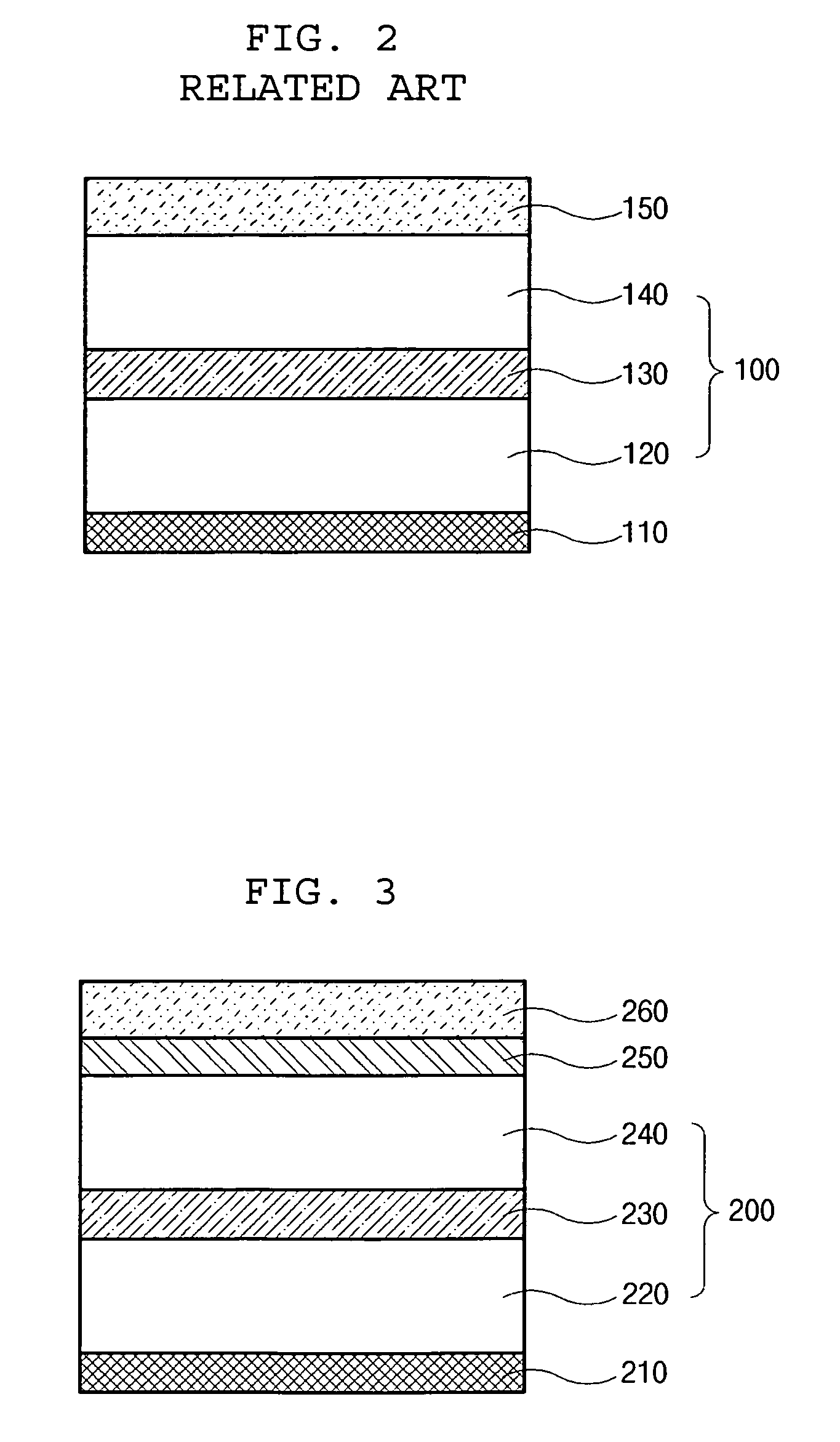
[0033]FIG. 3 is a cross-sectional view of a polarizer and a friction reducing layer for an LCD device according to the present invention.

[0034] As shown in FIG. 3, a polarizer 200 includes a polarizing layer 230, first and second protecting layers 220 and 240 on lower and upper surfaces (or inner and outer surfaces) of the polarizing layer 230. Further, an adhesive layer 210 on a lower surface (or inner surface) of the first protecting layer 220, a friction reducing layer 250 on an upper surface (or outer surface) of the second protecting layer 240, and a third protection film 260 on an upper surface (or outer surface) of the friction reducing layer 250. Though not shown in FIG. 3, a compensation layer compensating a light phase difference may be disposed between the friction reducing layer 250 and the second protecting layer 240. ...


PUM

PropertyMeasurementUnit
sizeaaaaaaaaaa
frictionaaaaaaaaaa
friction coefficientaaaaaaaaaa

Abstract

A liquid crystal display device includes first and second substrates facing each other and having a pixel region; a liquid crystal layer between the first and second substrates; a first polarizer on an outer surface of the second substrate; and a friction reducing layer on an outer surface of the first polarizer.

Description

[0001] The present invention claims the benefit of Korean Patent Application No. 2004-0034105, filed in Korea on May 14, 2004, which is hereby incorporated by reference. BACKGROUND OF THE INVENTION [0002] 1. Field of the Invention [0003] The present invention relates to a liquid crystal display device, and more particularly, to a liquid crystal display (LCD) device having a friction reducing layer. Although the present invention is suitable for a wide scope of applications, it is particularly suitable for improving display quality. [0004] 2. Discussion of the Related Art [0005] Until recently, display devices have generally used a cathode-ray tube (CRT). Presently, many efforts are being made to study and develop various types of flat panel displays, such as a liquid crystal display (LCD) device, a plasma display panel (PDP), a field emission display (FED), and an electro-luminescence display (ELD), as a substitute for CRTs. Of these flat panel displays, the LCD device has many adva...

Claims


Application Information

Patent Timeline
Patent Type & Authority Applications(United States)
IPC IPC(8): G02F1/1335G02F1/1333
CPCG02F1/1333G02F2203/64G02F2201/50F26B21/002F26B21/04F26B2200/10
Inventor PAIK, SANG-YOONLEE, SU-WOONGHONG, SEUNG-JIN
Owner LG DISPLAY CO LTD
Why Eureka
Try Eureka