
Control method for controlling the gas flow in a compressor

a compressor and gas flow technology, applied in the direction of positive displacement liquid engines, piston pumps, liquid fuel engines, etc., can solve the problems of large wear, slow closure/opening of gas flow, and large energy consumption, and achieve the effect of large wear and energy consumption

Inactive Publication Date: 2005-11-17
CARGINE ENG AB
View PDF8 Cites 10 Cited by
  • Summary
  • Abstract
  • Description
  • Claims
  • Application Information

AI Technical Summary

Benefits of technology

[0002] This type of compressor, of which there are a plurality of embodiments, but where the piston compressor is the most common one, is often called displacement compressor. In order to take advantage of the invention, the compressor should have a controllable inlet valve. However, it is preferred that the compressor also has a non return valve for inflow that can be turned off, and a controllable outlet valve. The invention provides for a varying need of pressurized gas with a reduced energy consumption and environment affection in relation to known methods.

Problems solved by technology

Frequent starts and stops will result in a large wear and will be energy consuming.
However, the closure / opening of the gas flow is relatively slow.
Moreover, a slow closure / opening will result in substantial flow losses.

Method used


Image

  • Control method for controlling the gas flow in a compressor
  • Control method for controlling the gas flow in a compressor

Examples


Embodiment Construction

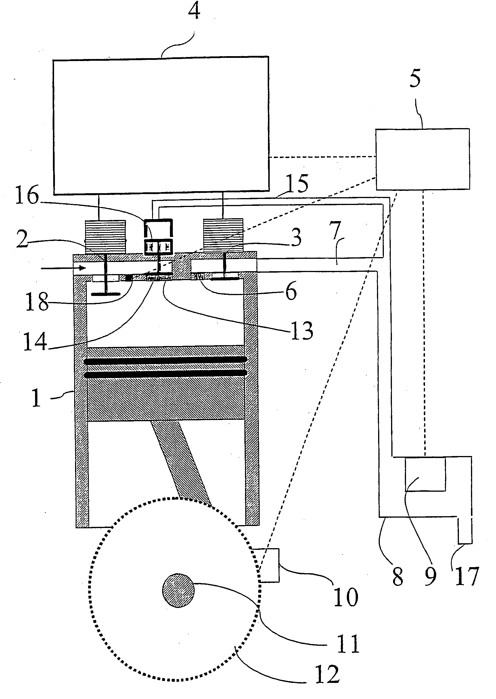
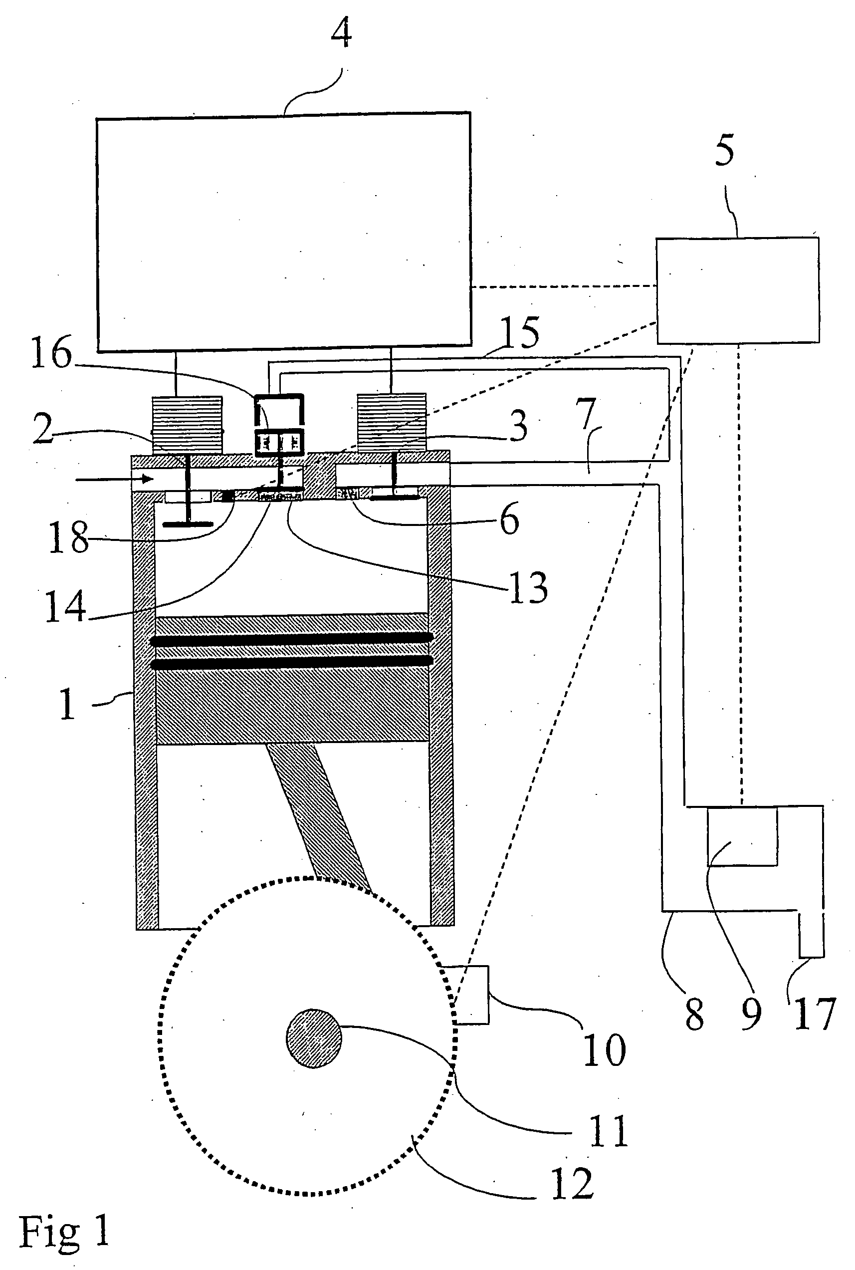
[0027]FIG. 1 is an exemplifying, schematic picture that shows a compressor cylinder with a-piston 1. The piston is under movement during an intake stroke, and air (or any other gas) is flowing through the open inlet valve 2. The inlet valve 2 and the closed outlet valve 3 are constituted by controllable valves that are pneumatically, hydraulically or electromagnetically operable. A circuit 4 is used for operating the valves 2 and 3. A control unit 5 is operatively connected with the circuit 4 for signal control of the circuit and the valves 2 and 3 that are connected to the circuit. Air that is compressed is transported through the outlet valve 3 and / or a non return valve for the outflow of gas 6 through a conduit 7 to a tank 8. By means of a sensor 9 in the tank 8, which is operatively connected to the control unit 5, the control unit is provided with continuous information about the pressure in the tank. A sensor 10, arranged at a graduated arc 12, mounted on the compressor shaft ...


PUM


Abstract

A control method for controlling the gas flow by a compressor in which a volume is expanded during an intake stroke and the intaken volume of gas is compressed and taken out through a non return valve (6) for outflow and / or an operable outlet valve (3) during an evacuation stroke, and in which the compressor has a controllable inlet valve (2) that is pneumatically, hydraulically or electromagnetically operable and that is opened and closed upon basis of a signal from a control system. The inlet valve (2) is kept closed during at least a part of an intake stroke.

Description

THE FIELD OF THE INVENTION [0001] The present invention relates to a control method for controlling the gas flow in a compressor in which a volume is expanded during an intake stroke and an introduced volume of gas is compressed and taken out through a non return valve for outflow and / or an operable valve during an evacuation stroke, the compressor having a controllable inlet valve that is pneumatically, hydraulically or electromagnetically operated and that is opened and closed upon basis of a signal from a control system. [0002] This type of compressor, of which there are a plurality of embodiments, but where the piston compressor is the most common one, is often called displacement compressor. In order to take advantage of the invention, the compressor should have a controllable inlet valve. However, it is preferred that the compressor also has a non return valve for inflow that can be turned off, and a controllable outlet valve. The invention provides for a varying need of press...

Claims


Application Information

Patent Timeline
Patent Type & Authority Applications(United States)
IPC IPC(8): F04B49/06F04B49/24F04B49/03
CPCF04B49/24F04B49/065F04B49/06F04B49/22F04B53/14F04B49/03F05B2210/12Y10S417/00
Inventor HEDMAN, MATS
Owner CARGINE ENG AB
Learn More