
Thermal sensing with bridge circuitry

a bridge circuit and thermal sensing technology, applied in the direction of instruments, heat measurement, material heat development, etc., can solve the problems of a number of limitations of the previous thermal sensing technology with bridges

Inactive Publication Date: 2005-11-17
PALO ALTO RES CENT INC
View PDF47 Cites 29 Cited by
  • Summary
  • Abstract
  • Description
  • Claims
  • Application Information

AI Technical Summary

Problems solved by technology

Previous techniques in thermal sensing with bridges have a number of limitations.

Method used


Image

  • Thermal sensing with bridge circuitry
  • Thermal sensing with bridge circuitry
  • Thermal sensing with bridge circuitry

Examples


Embodiment Construction

[0028] The below-described implementations can be applied in measuring thermal effects of chemical reactions as well as in various other ways, some of which are described in the parent application, incorporated herein by reference. In describing some implementations, the terms “target molecule”, “ligand”, “test ligand”, “target protein”, and other terms are used herein with substantially the same meanings as set forth in the parent application.

[0029] As used herein, the term “thermal change” encompasses the release of energy in the form of heat or the absorption of energy in the form of heat.

[0030] As used herein, a “nanocalorimeter” is a calorimeter capable of measuring in the range of nanocalories. Exemplary implementations of the present invention can be applied generally in calorimeters and calorimeter arrays. More specifically, implementations can be applied in nanocalorimeters and nanocalorimeter arrays that enable measurement of enthalpic changes, such as enthalpic changes ...


PUM


Abstract

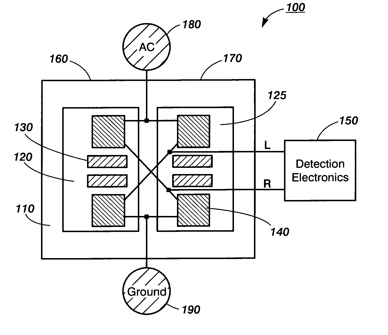
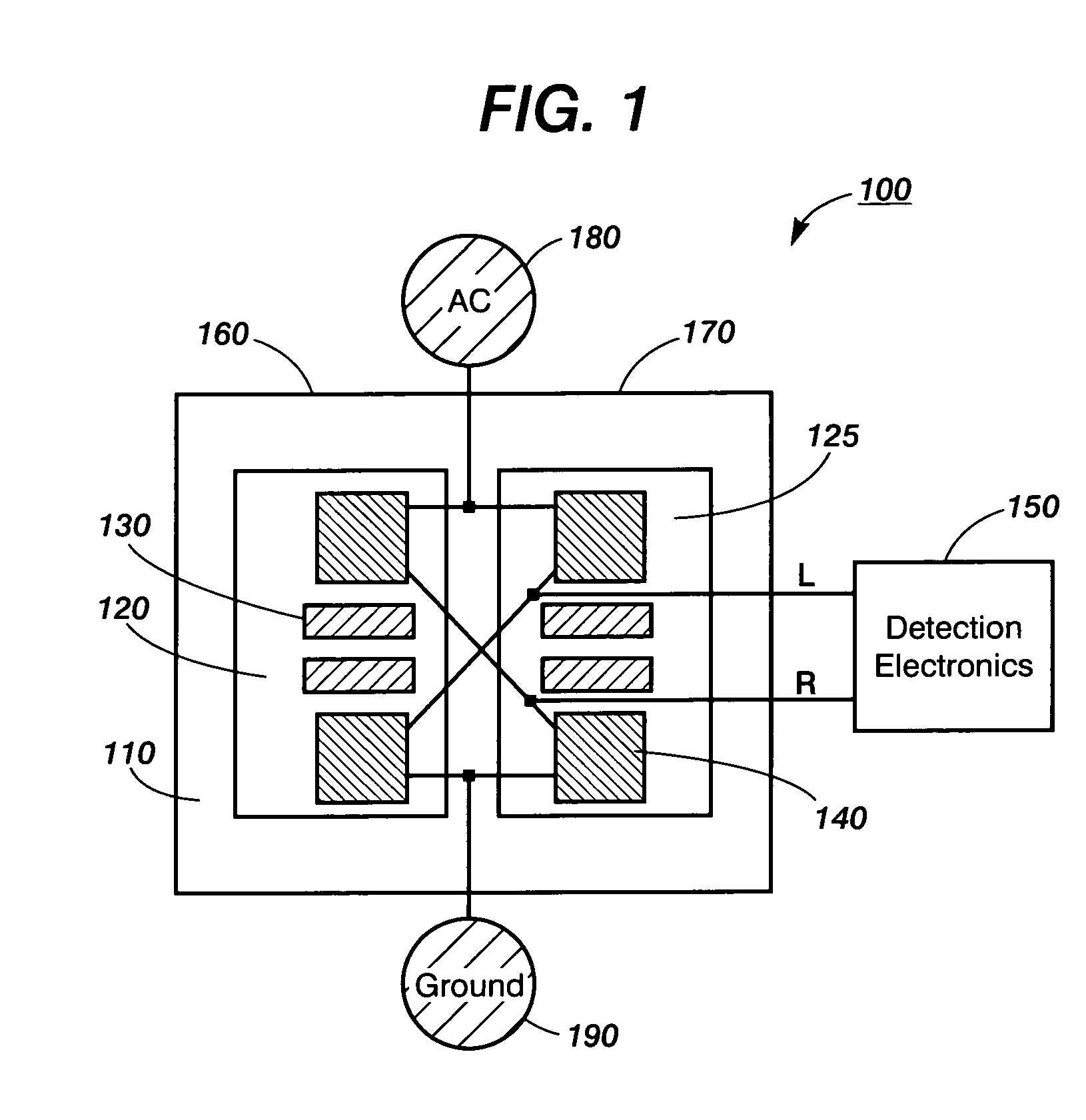
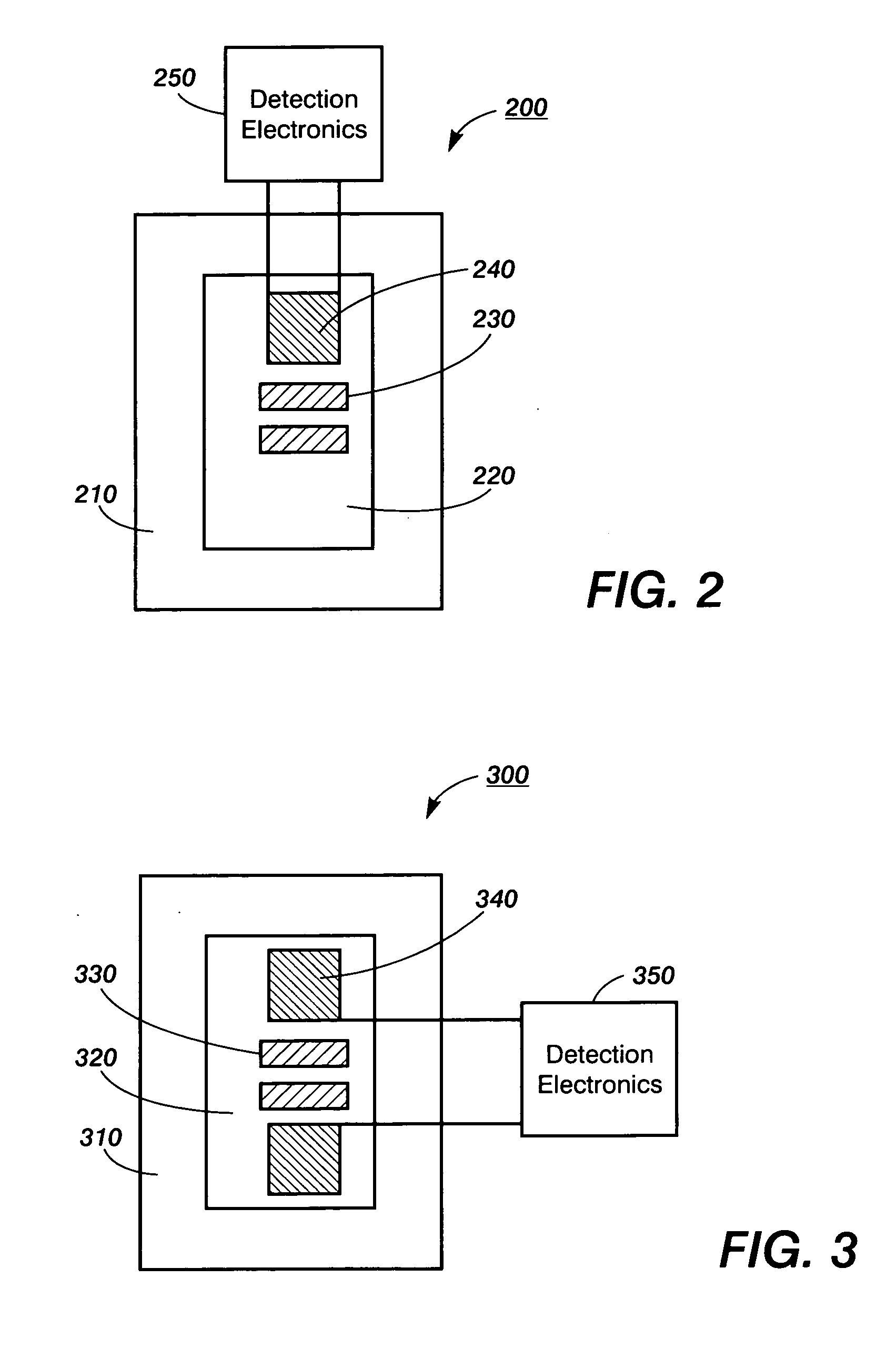
Thermal sensing devices can include two subsets of thermal sensors connected in a bridge by circuitry on the same support layer or surface with the sensors. Each thermal sensor can be formed in a patterned layer of semiconductor material, and the bridge circuitry can include leads formed in a patterned layer of conductive material, over or under the semiconductor layer. In one implementation, the bridge circuitry includes conductive portions that extend across and electrically contact the lower surface of each sensor's semiconductor slab. The bridge circuitry can also include pads that can be electrically contacted, such as by pogo pins. The device's reaction surface can be spaced apart from or over the thermal sensors. The device's components can be shaped and positioned so that the bridge's offset voltage is below the sensitivity level required for an application, such as by left-right symmetry about an axis.

Description

RELATED APPLICATIONS [0001] This application is a continuation-in-part of pending U.S. patent application Ser. No. 10 / 114,611 (U.S. Patent Application Publication No. 2003 / 0186453) (“the parent application”), which is incorporated herein by reference in its entirety. Other continuations-in-part of the parent application include U.S. patent application Ser. No. 10 / 303,446 (U.S. Patent Application Publication No. 2003 / 0186454) and Ser. No. 10 / 303,500 (U.S. Patent Application Publication No. 2003 / 0186455), both of which are incorporated herein by reference in their entireties.BACKGROUND OF THE INVENTION [0002] The present invention relates generally to techniques that sense thermal stimuli. In particular, implementations employ thermometer elements or other thermal sensors connected by bridge circuitry into a bridge. Such bridges can be used, for example, in a calorimeter, a term used herein to refer to any device or apparatus that measures quantities of absorbed or evolved heat or det...

Claims


Application Information

Patent Timeline
IPC IPC(8): G01F1/68G01K1/00G01K7/30G01K17/00G01N25/20G01N25/48G01N27/00
CPCG01K7/30G01N25/482G01K17/00
Inventor BELL, ALANBRUCE, RICHARD H.PEETERS, ERICWOLKIN, MICHAL V.BRUYKER, DIRK DE
Owner PALO ALTO RES CENT INC
Learn More