

Hydraulic tensioner
a technology of hydraulic tensioner and tension ball, which is applied in the direction of mechanical equipment, belts/chains/gearrings, etc., can solve the problems of irregular and violent movement of check ball, inability to achieve adequate follow-up properties, and difficulty in maintaining adequate follow-up properties, etc., to suppress violent motion, maintain tension, and achieve accurate follow-up properties
- Summary
- Abstract
- Description
- Claims
- Application Information
AI Technical Summary
Benefits of technology
Problems solved by technology
Method used
Image

Examples
Embodiment Construction
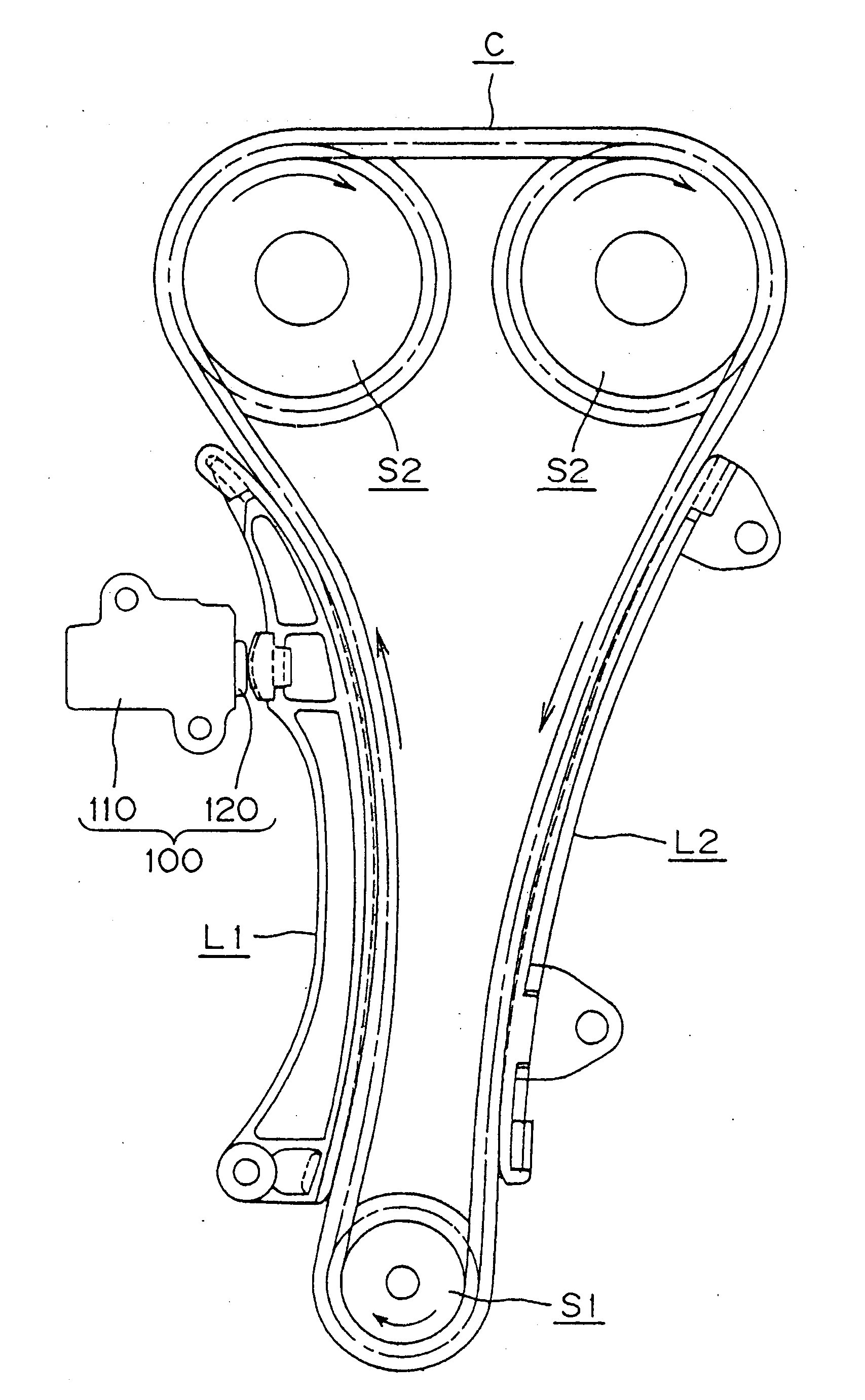
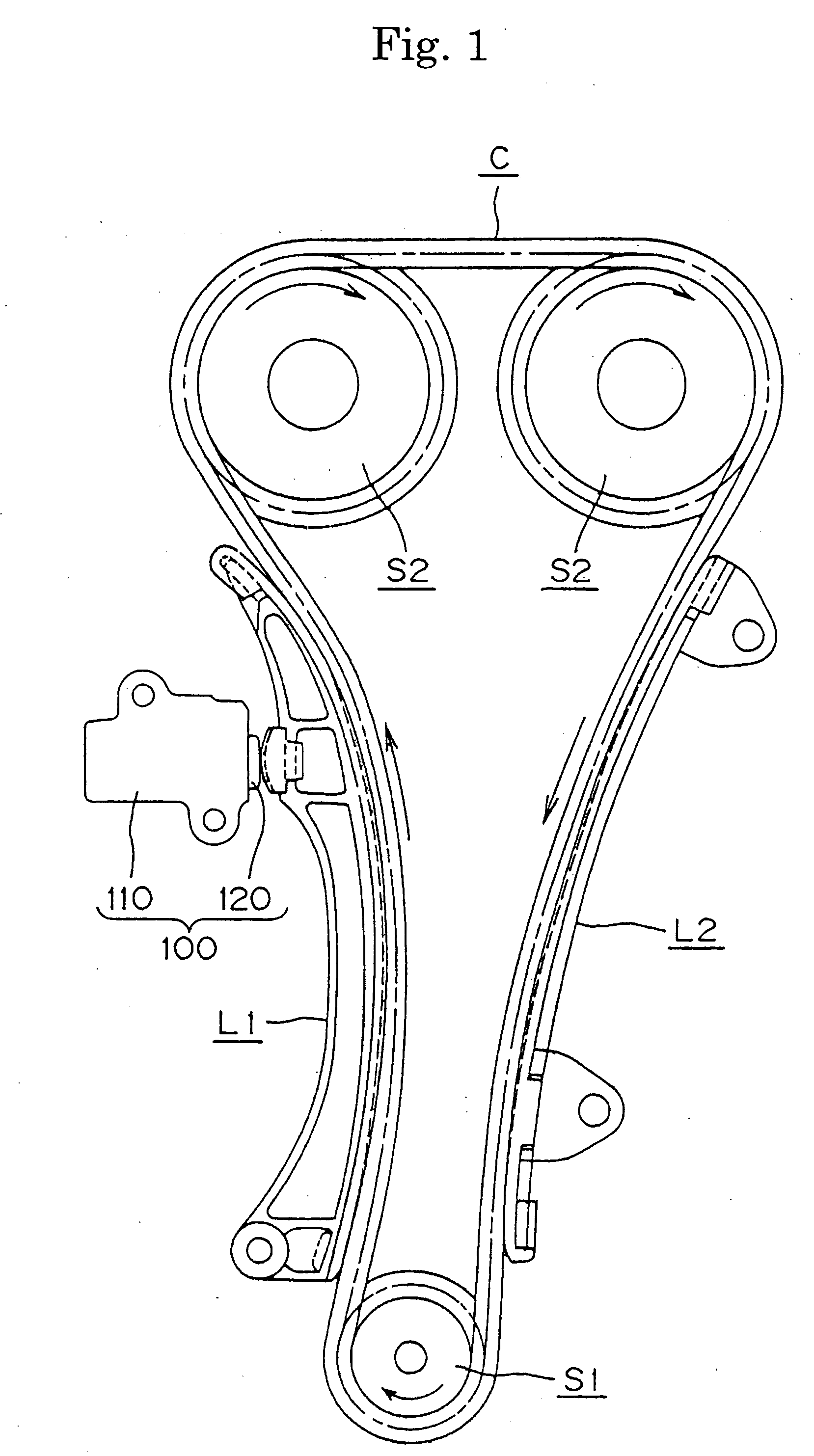
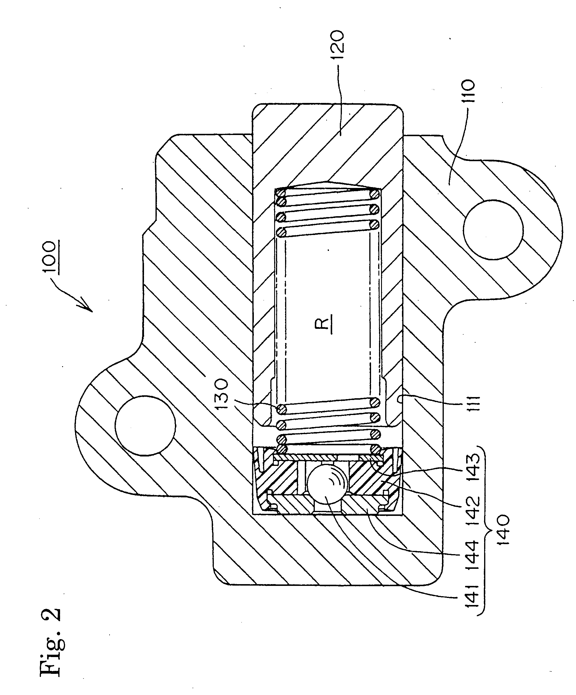
[0017] As shown in FIGS. 1 and 2, a hydraulic tensioner 100, which is attached to an engine body (not shown), applies tension to the slack side of a timing chain C, which meshes with a driving sprocket S1, rotated by a crankshaft, and two driven sprockets S2, each fixed to and rotatable with one of a pair of camshafts. A plunger 120 is protrudes slidably from a front end of the tensioner body 110, and the plunger applies tension to the chain C through a pivoted lever L1 by pressing the back of the lever at a location remote from the pivoted end of the lever. A fixed guide L2 guides the travel of the tension side of the timing chain C. Arrows indicate the direction of chain movement and the direction of rotation of the sprockets.
[0018] As shown in FIG. 2, the plunger 120, the outside of which is substantially cylindrical, fits slidably into a plunger-accommodating hole 111 formed in the housing 110. A plunger-biasing coil spring 130 is located in a high pressure oil chamber R, which...
PUM
 Abstract
Description
Claims
Application Information