
Sphygmomanometer with three-dimensional positioning function

a three-dimensional positioning and sphygmomanometer technology, applied in the field of sphygmomanometer with a three-dimensional positioning function, can solve the problem of incorrect positioning of the measuring cuff or the related part of the tester's body, and achieve the effect of more accurate blood measurement taken by the user

Active Publication Date: 2005-11-17
HEALTH & LIFE CO LTD
View PDF8 Cites 33 Cited by
  • Summary
  • Abstract
  • Description
  • Claims
  • Application Information

AI Technical Summary

Benefits of technology

"The present invention is a sphygmomanometer with a 3D positioning function. It includes a microprocessor chip and a 3D acceleration sensor chip. The sensor chip detects the position of the measuring cuff and sends the data to the microprocessor chip. The microprocessor chip compares the data with pre-set parameters and alerts the tester if the position is incorrect. This ensures accurate blood pressure readings. The sphygmomanometer also has a display device connected to the microprocessor chip, allowing the tester to view the blood pressure measurement results. The 3D acceleration sensor chip is a semiconductor chip with a piezoelectric transformer and a bridge type sensor. The chip detects changes in the position of the measuring cuff and sends the data to the microprocessor chip. The microprocessor chip compares the data with pre-set parameters and alerts the tester if the position is incorrect. This ensures accurate blood pressure readings."

Problems solved by technology

If the values of the detected parameters fall beyond the predetermined range of related parameters, then the position of the measuring cuff of the sphygmomanometer or the related part of the tester's body is incorrect.

Method used


Image

  • Sphygmomanometer with three-dimensional positioning function
  • Sphygmomanometer with three-dimensional positioning function
  • Sphygmomanometer with three-dimensional positioning function

Examples


Embodiment Construction

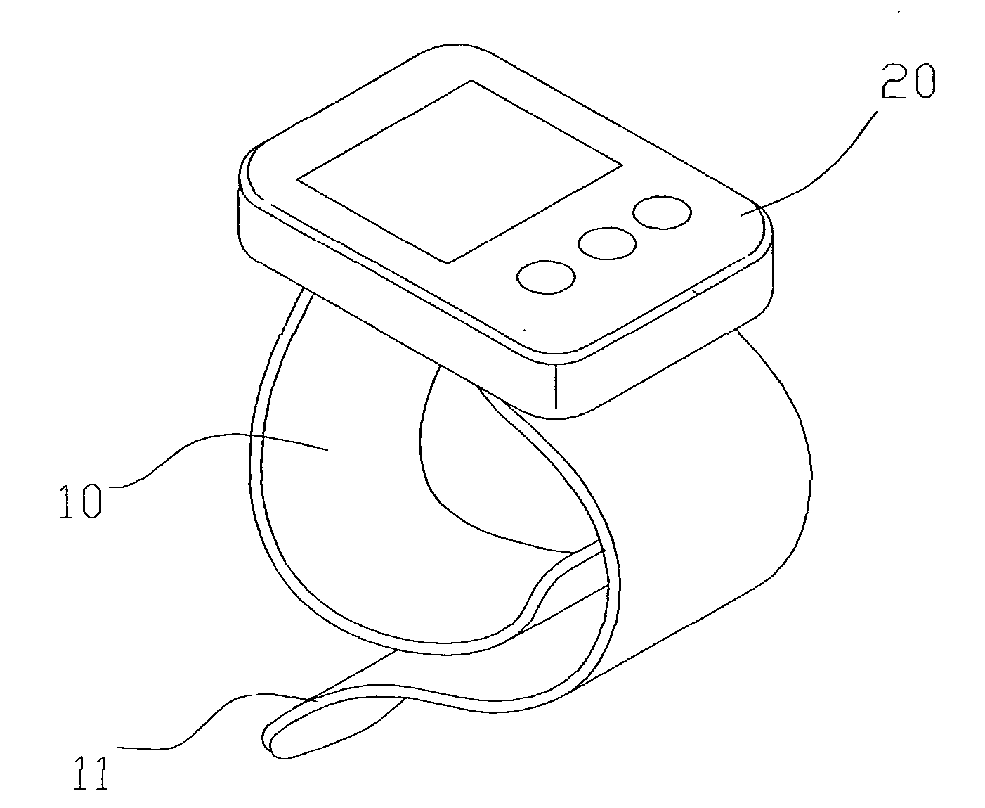
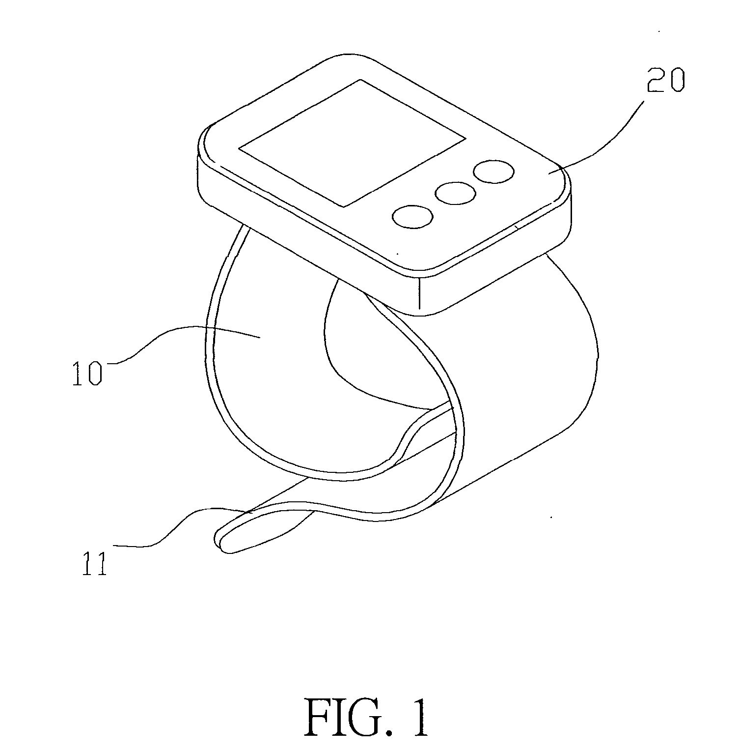
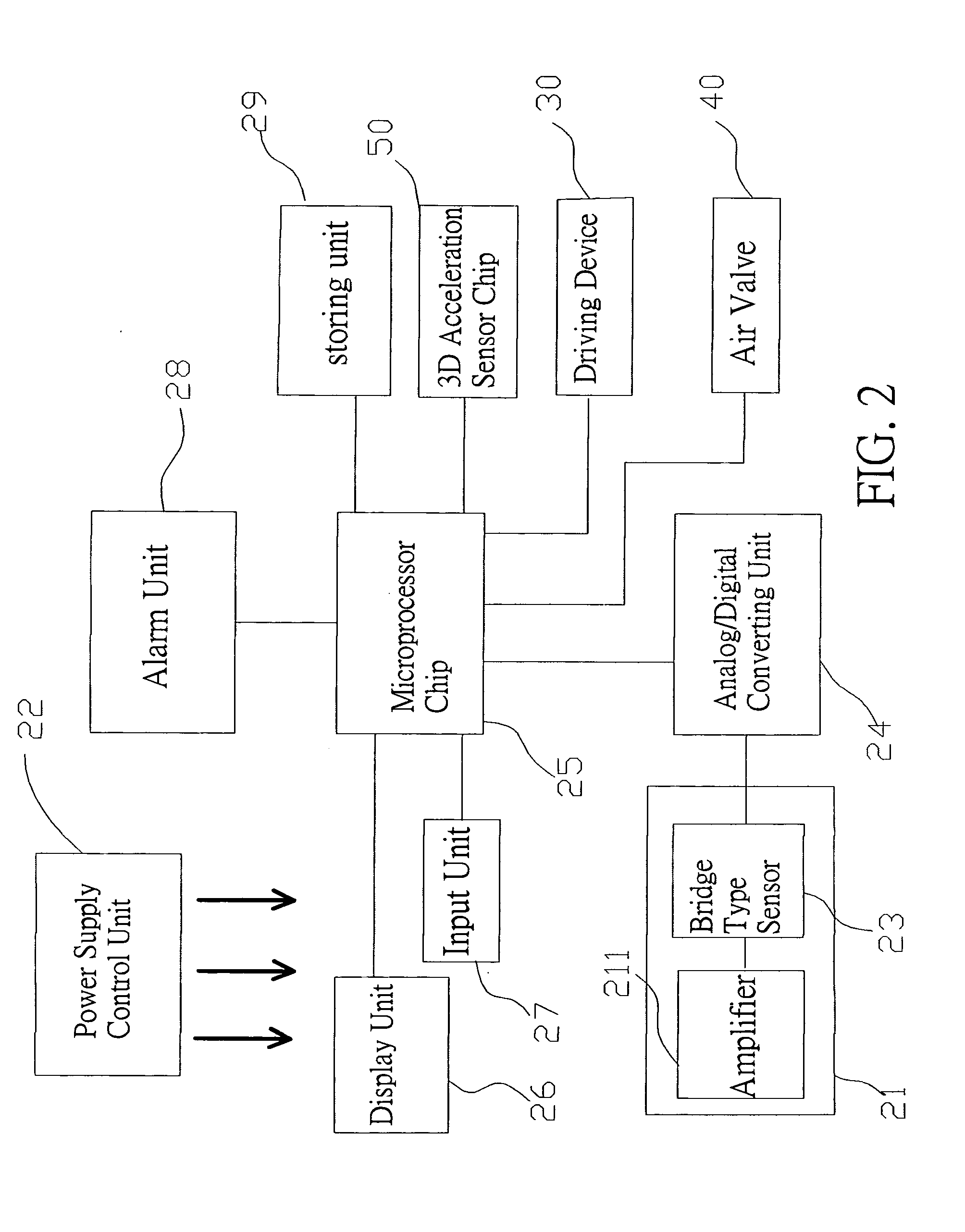
[0018] Please refer to FIGS. 1, 2 and 3 for the sphygmomanometer having 3D space positioning function, and the invention uses a wrist sphygmomanometer for example. The sphygmomanometer comprises an airbag cuff 10, an adhesive tape 11 individually adhered on both ends of the airbag cuff 10 for the adhesion, a housing 20 disposed on the airbag cuff, and a pressure sensor 21 disposed in the housing 20. A pressure difference is used to detect a change in blood pressure. Such pressure sensor 21 includes an amplifier 211 and a bridge type sensor 23; wherein the input end of the amplifier 211 is connected to a power supply unit 22 and a resistor 212, and the output end of the amplifier 211 is connected to the bridge type sensor 23, such that the result detected by the pressure sensor 21 is amplified by the amplifier 211, and the voltage is outputted by the bridge type sensor 23.

[0019] The bridge type sensor 23 is also connected to an analog / digital converting unit 24 which comprises a plu...


PUM


Abstract

The present invention discloses a sphygmomanometer having 3D positioning function, which comprises a microprocessor chip which is coupled individually to a microprocessor chip which is coupled individually to a pressure sensor, an alarm unit, a storing unit, a 3D acceleration sensor chip, a display device, a driving device, and an air valve, so that when a person's blood pressure is measured, the 3D acceleration sensor chip detects the spatial position of the measuring cuff of the sphygmomanometer and sends the parameters related to the detected spatial position to the microprocessor chip. In the meantime, the microprocessor chip will retrieve a predetermined range of the parameters related to the spatial position from the storing unit, and compare such range with the value of the detected parameters. If the values of the detected parameters fall beyond the predetermined range of parameters, the microprocessor chip will issue an alarm through the alarm unit until the spatial position is correct. Thus the person who takes blood pressure measurement can always get the most accurate measurement.

Description

BACKGROUND OF THE INVENTION [0001] 1. Field of the Invention [0002] The present invention relates to a sphygmomanometer with a three-dimensional (3D) positioning function, more particularly to a sphygmomanometer which uses a 3D acceleration sensor chip to detect the spatial position of a measuring cuff of the sphygmomanometer and send the parameters of the detected spatial position to the chip processor, such that after the comparison of the parameters, the tester can move the measuring cuff of the sphygmomanometer or the posture of a related part of the tester body to the correct spatial position. [0003] 2. Description of the Related Art [0004] In general, sphygmomanometers are divided into a traditional mercury type and an electronic type; wherein the mercury type is not only time-consuming, but it also requires professionally trained and experienced people to correctly measure a blood pressure. On the other hand, electronic sphygmomanometers are further divided into a desktop typ...

Claims


Application Information

Patent Timeline
Patent Type & Authority Applications(United States)
IPC IPC(8): A61B5/02A61B5/022
CPCA61B5/681A61B5/022
Inventor YANG, PAUL
Owner HEALTH & LIFE CO LTD
Learn More