Catheter with removable extension

a catheter and extension technology, applied in the field of catheters with removable extension, can solve the problems of increased patient's risk of blood loss, air embolism, or infection, unprotected lumens, etc., and achieve the effects of preventing infection, reducing backflow, and facilitating disengagemen

Active Publication Date: 2005-11-17
CR BARD INC
View PDF29 Cites 255 Cited by
  • Summary
  • Abstract
  • Description
  • Claims
  • Application Information

AI Technical Summary

Benefits of technology

[0014] The implementation of the catheter valve assembly and its corresponding extension leg unit provides various advantages, which may include one or more of the following: (1) the removable extension leg unit may allow the physician to easily disengage multiple fluid infusion lines to a catheter, while simultaneously sealing all access ports without additional efforts; (2) the catheter valve assembly may prevent infection, limit backflow, and minimize embolism by keeping the proximal end of the catheter closed except when accessed by the extension leg unit or the corresponding access cannula; (3) the catheter with the proximal end valve assembly may improve patient safety by insuring that the proximal end of the catheter is closed except when it is properly accessed; (4) the catheter with the valve assembly may be accessed multiple times without requiring replacement; (5) in some variations the catheter valve assembly may allow selective access of individual lumen while keeping the unused lumens sealed; (6) the catheter valve assembly may have built-in safety features to prevent accidental opening of the valve; and (7) because a blood clot begins to form when blood is exposed to air, the automatic closure of the valves immediately upon disengagement of the removable extension leg unit or the access cannula may minimize coagulation within the catheter lumen.

Problems solved by technology

However, in case of accidental separation of the valve cap from the catheter, the distal end of the catheter would then be exposed to the environment outside the body of the patient.
The exposed catheter lumen may increase the patient's risk of blood loss, air embolism, or infection.
The use of a cap or adapter to seal the proximal end of a catheter may increase the risk of trapping air pockets within the lumen of the catheter, resulting in an air embolism.
Furthermore, during a treatment process requiring infusion of multiple fluids through the implanted catheter, the physician may inadvertently leave the lumens unprotected between procedures, and expose one or more of the lumens to possible contaminations.

Method used


Image

  • Catheter with removable extension
  • Catheter with removable extension
  • Catheter with removable extension

Examples


Embodiment Construction

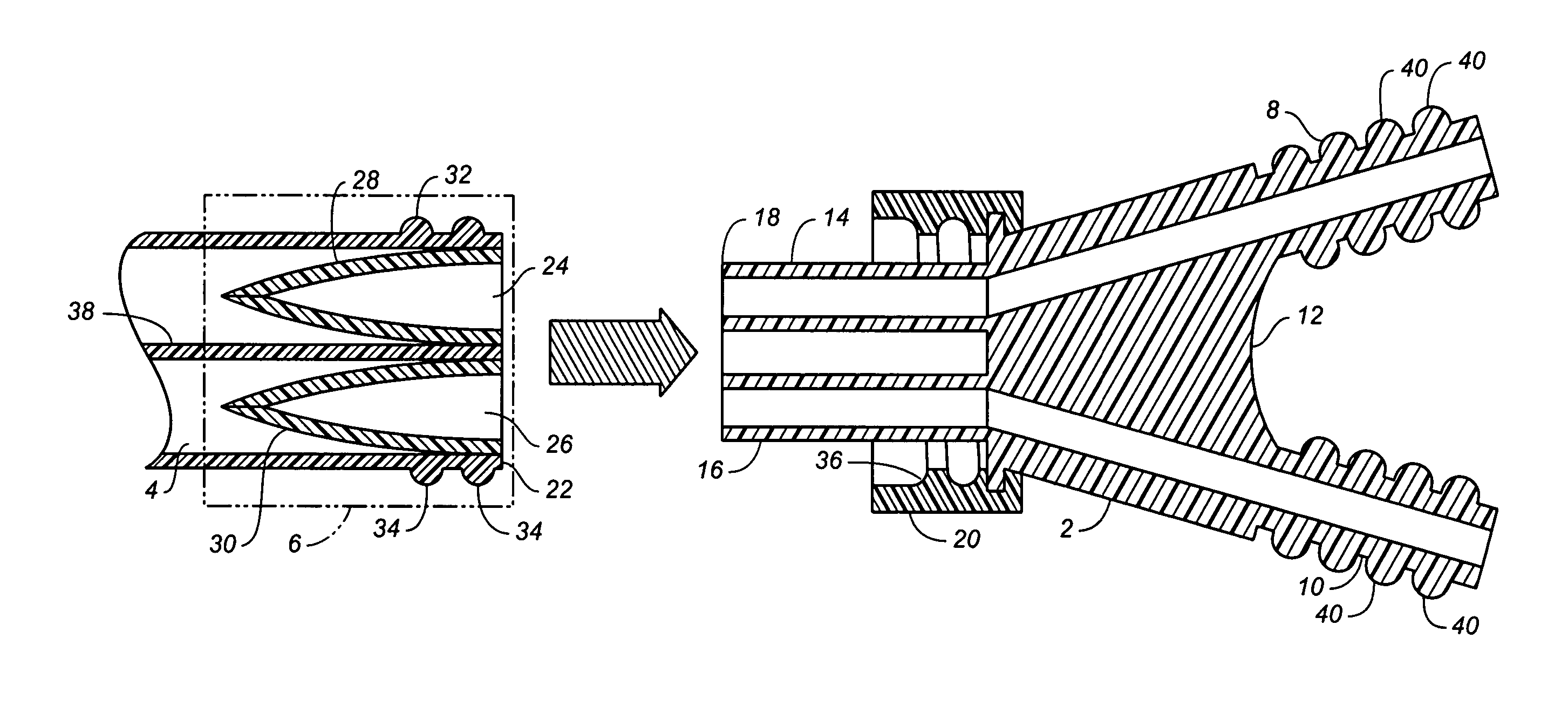
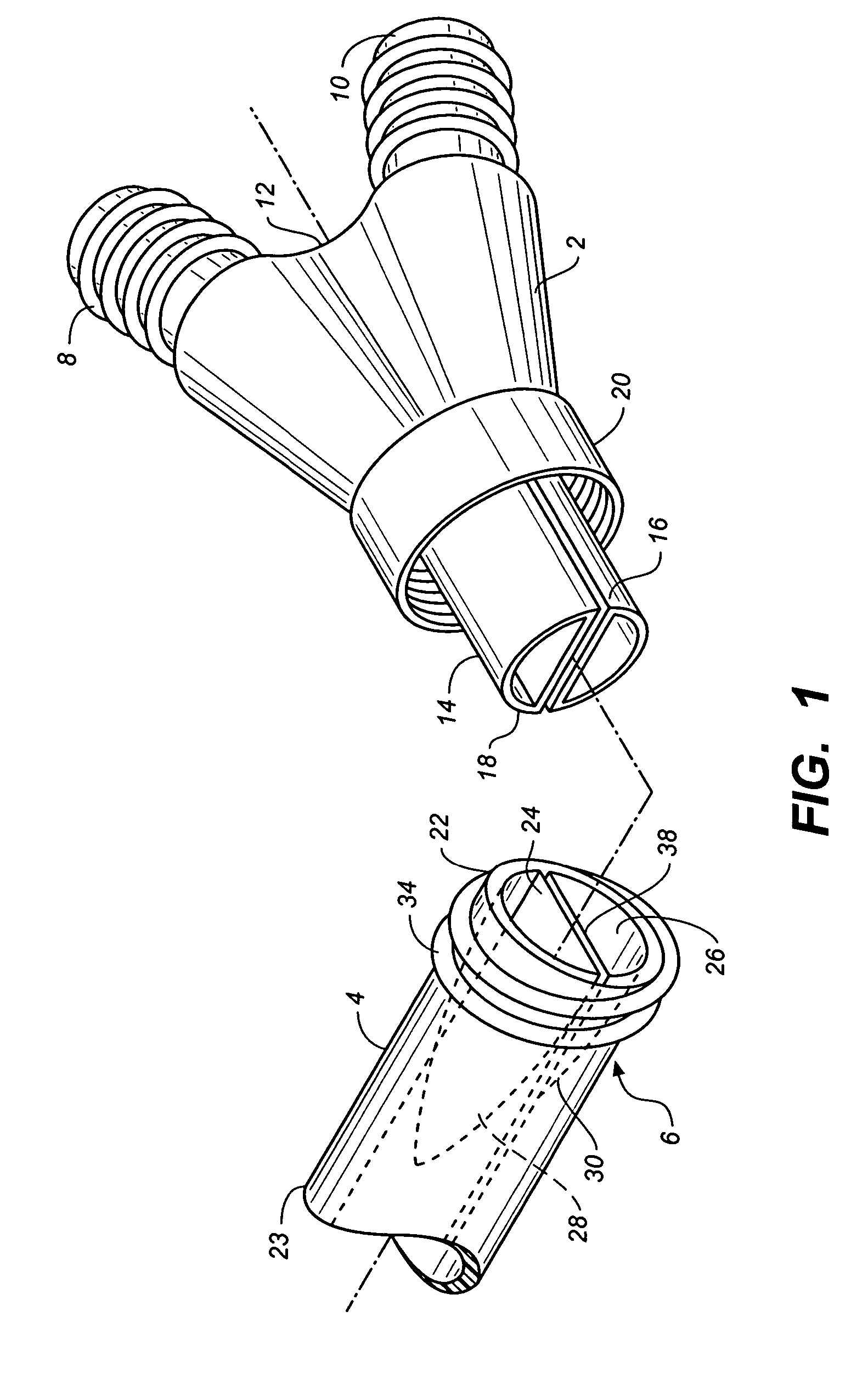
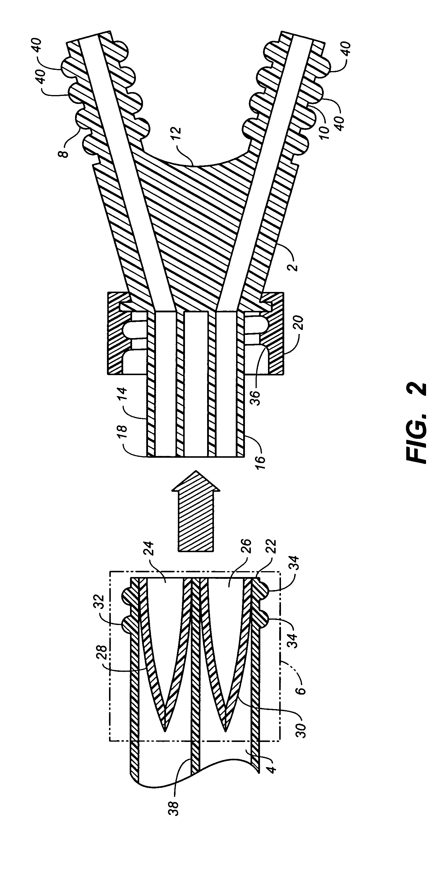
[0072] The following detailed description should be read with reference to the drawings, in which like elements in different drawings may be identically numbered. The drawings, which are not necessarily to scale, depict selected embodiments and are not intended to limit the scope of the invention. The detailed description illustrates by way of example, not by way of limitation, the principles of the invention. This description will clearly enable one skilled in the art to make and use the invention, and describes several embodiments, adaptations, variations, alternatives and uses of the invention, including what is presently believed to be the best mode of carrying out the invention.

[0073] Before describing the present invention, it is to be understood that unless otherwise indicated this invention need not be limited to applications in humans. As one of ordinary skill in the art would appreciate, variations of the invention may be applied to other mammals as well. Moreover, it sho...


PUM


Abstract

Catheter valve assemblies and methods for connecting catheters and/or providing fluid access to catheters. In one variation, a device comprises a catheter valve assembly and an extension leg unit. The extension leg unit includes lumen inserts for engaging valves positioned within the catheter valve assembly. In another variation, the valve assembly comprises a depressable plunger which may be engaged by an access cannula. Various connectors with integrated valve assemblies are also disclosed.

Description

CROSS-REFERENCE TO RELATED APPLICATIONS [0001] This application is a continuation-in-part of pending U.S. patent application Ser. No. 10 / 844,236 entitled “Valved Connector” filed May 12, 2004, and a continuation-in-part of pending U.S. patent application Ser. No. 10 / 844,276 entitled “Hemostasis Valve for a Catheter” filed May 12, 2004, each of which is incorporated herein by reference in its entirety.STATEMENT REGARDING FEDERALLY SPONSORED RESEARCH OR DEVELOPMENT [0002] Not applicable. REFERENCE TO A COMPACT DISK APPENDIX [0003] Not applicable. BACKGROUND OF THE INVENTION [0004] There are a variety of conditions that require injection of fluids into, or withdrawal of fluids from, a patient's circulatory system. It is common to use an implanted catheter to repeatedly access the patient's vascular system. A flexible guidewire placed in the vascular system may be used to facilitate placement of the catheter, but its use would prevent the physician from capping the proximal end of the c...

Claims


Application Information

Patent Timeline
Patent Type & Authority Applications(United States)
IPC IPC(8): A61M5/00A61M25/00A61M39/06A61M39/26
CPCA61M25/0075A61M2039/268A61M39/045A61M39/06A61M39/0606A61M39/1011A61M39/105A61M39/162A61M39/223A61M39/26A61M2039/062A61M2039/0673A61M2039/1077A61M2039/1083A61M2039/1088A61M2039/1094A61M25/0097
Inventor DIFIORE, ATTILIO E.ROME, GUY
Owner CR BARD INC
Why Eureka
Try Eureka