Auxiliary device for a weapon and attachment thereof

a technology for auxiliary devices and weapons, applied in the field of auxiliary devices for weapons, can solve the problems of time-consuming, time-consuming operation, and time-critical safety of attaching and detaching these devices, and achieve the effect of preventing the rotation of the rotatable member and facilitating the ease with which an auxiliary device can be reliably secured to a weapon

Inactive Publication Date: 2005-11-24
L 3 COMM INSIGHT TECH
View PDF0 Cites 83 Cited by
  • Summary
  • Abstract
  • Description
  • Claims
  • Application Information

AI Technical Summary

Benefits of technology

[0033] Preferably at least a portion of the second positioning mechanism comprises a spring-loaded projection that projects from either the auxiliary device or the weapon into a portion of the other, without having to manually depress the projection. This facilitates the ease with which an auxiliary device can be reliably secured to a weapon. To remove the auxiliary device from the weapon, the spring biasing the second positioning mechanism is manually depressed (or otherwise moved) to allow disengagement of the second positioning mechanism. Then, the auxiliary device may be slid forward for removal from the weapon.
[0034] According to another embodiment, the auxiliary device has a spring-biased mechanism that enables it to be secured to weapons having different dimensions from the front of the trigger guard to the transverse slot along the lower surface of the dust cover.
[0035] According to another embodiment, the auxiliary device has a rotatable member that can accommodate a range of rail dimensions and has a locking mechanism for preventing rotation of the rotatable member.

Problems solved by technology

Further, such systems typically require use of two hands to mount the device on the weapon, with both hands performing a function beyond merely gripping the weapon.
Moreover, attachment and detachment of these devices can be time consuming and, in law enforcement and military applications, such time may be critical to the safety of the weapon's operator or others.
As a result of these and other problems with conventional devices, the user typically leaves the auxiliary device mounted on the weapon or performs a time consuming operation to mount the device when needed.
These alternatives are undesirable.
Also, in the context of handweapons, for example, many holsters do not readily accommodate weapons having auxiliary devices mounted thereon.
Thus, it is often difficult to holster or carry a weapon having such a device attached to it.
This presents special problems for law enforcement officers and others.
Additionally, the user may not want to use the device during daylight hours, but may want to attach the device to a weapon at night.
Moreover, depending on the configuration of the auxiliary device, the user may need to replace its batteries.
Another problem with conventional auxiliary devices is that the device is often wider than the weapon, or the device protrudes beyond the front end of the weapon.
These characteristics often result in subjecting the auxiliary device to greater wear and tear because the auxiliary device often contacts various obstructions in the environment where the weapon is being used.
For instance, a device extending beyond the end of a barrel of a weapon may collide with doorways, clothing, tree branches, or other objects, tending to tear the device apart from the weapon and possibly damaging, or rendering inoperable, the device or the weapon itself.
Another problem is that an assailant may more easily disarm a user by grabbing an auxiliary device which extends substantially beyond the weapon.
The danger of these and other problems occurring are greater at night or when ordinary vision is impaired.
Additionally, many prior auxiliary devices, especially illuminators, are bulky.
This characteristic also is undesirable.
While the '967 Patent overcomes some of the problems traditionally associated with the attachment of an auxiliary device to a weapon, it too leaves room for improvement.
This flexible attachment is not ideal in some circumstances, for example, for use with auxiliary devices requiring precise boresight alignment.
Also, the attachment mechanism is relatively bulky, causing the auxiliary device to be relatively wider, resulting in an increase in the size of the device in at least one dimension.
Moreover, the engagement of portions of the auxiliary device with the corresponding portions of the weapon is limited by the degree of flexibility of the flexible mechanism.
Furthermore, the spring-loaded mechanism also limits the biasing force holding the auxiliary device to a weapon.
As a result, this attachment approach may be successful on weapons, such as handweapons, which have relatively modest recoil forces, but may be somewhat less successful on other weapons, such as shotguns, where the greater recoil forces may cause the auxiliary device to dislodge from the weapon.
While lights and other devices primarily have been mounted to weapons, many weapons are not specifically designed to facilitate this.
As a result, special brackets and other mounting devices often need to be used.
Some weapons have mounting racks, but various drawbacks exist even with these types of devices.
In many cases, it is difficult to mount a device to the weapon and / or complex mechanical structures are necessary.
This difference in dimension may cause an auxiliary device not to fit on to the weapon because the back end of the auxiliary device contacts the front surface of the trigger guard before a spring-biased mechanism can engage in the transverse slot.
Alternatively, the difference in dimension may cause the auxiliary device to unnecessarily extend past the end of the weapon.
This requires the owner to store a second part and adds to the manufactured cost.
This can cause an auxiliary device to fit nicely on some weapons and either be too tight or too loose on another weapon.
Other problems and drawbacks with prior approaches exist.

Method used


Image

  • Auxiliary device for a weapon and attachment thereof
  • Auxiliary device for a weapon and attachment thereof
  • Auxiliary device for a weapon and attachment thereof

Examples


Embodiment Construction

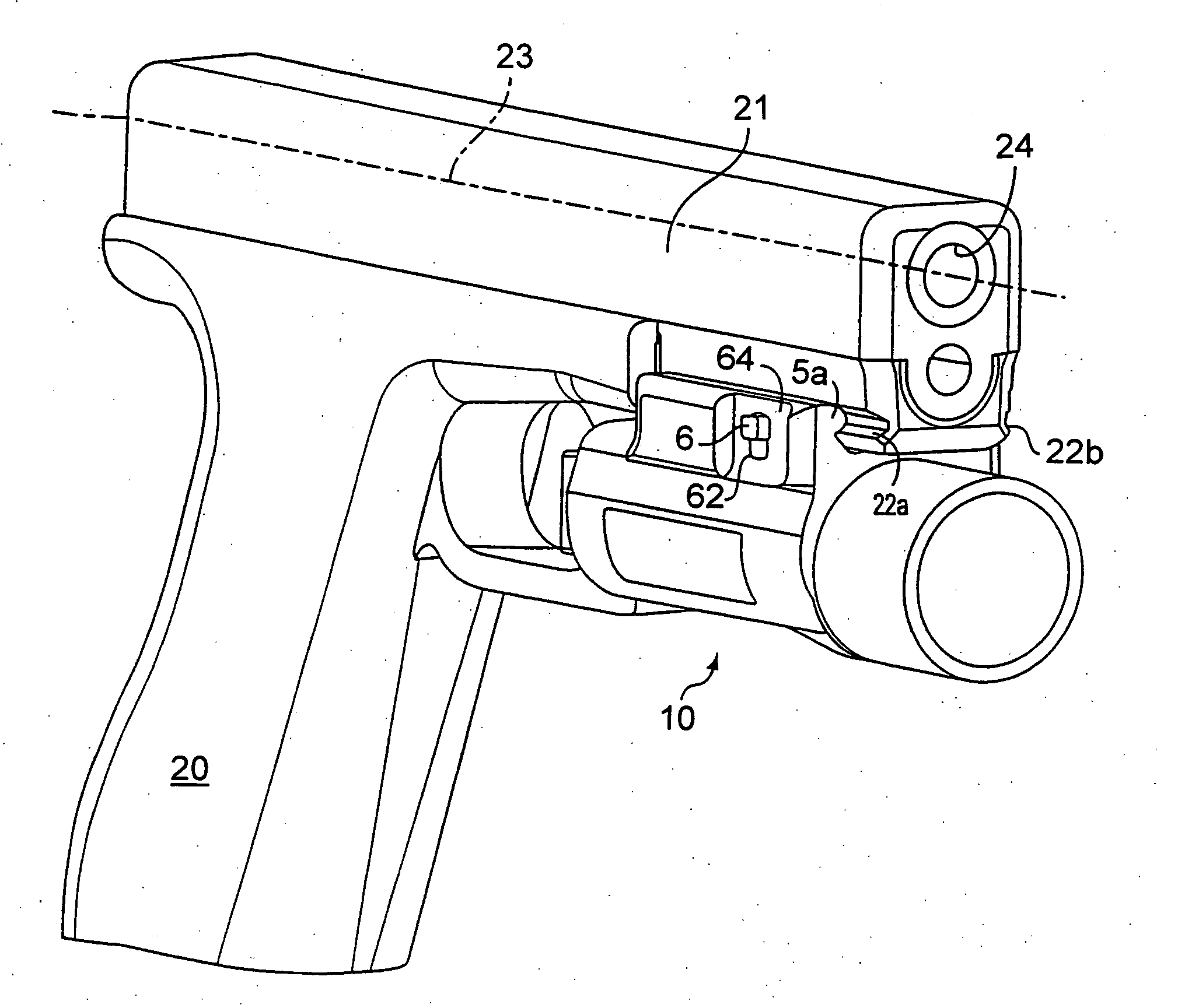
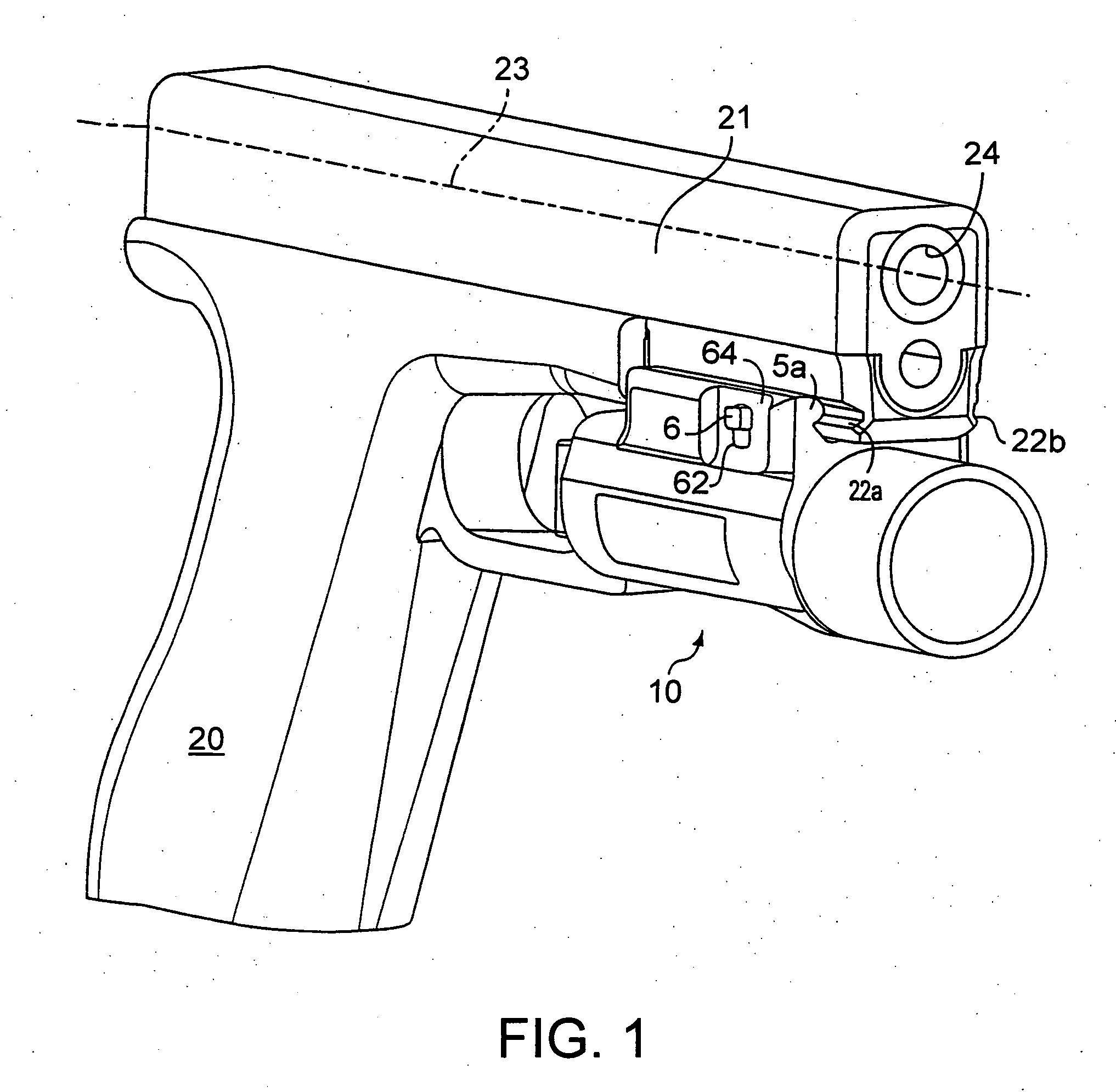
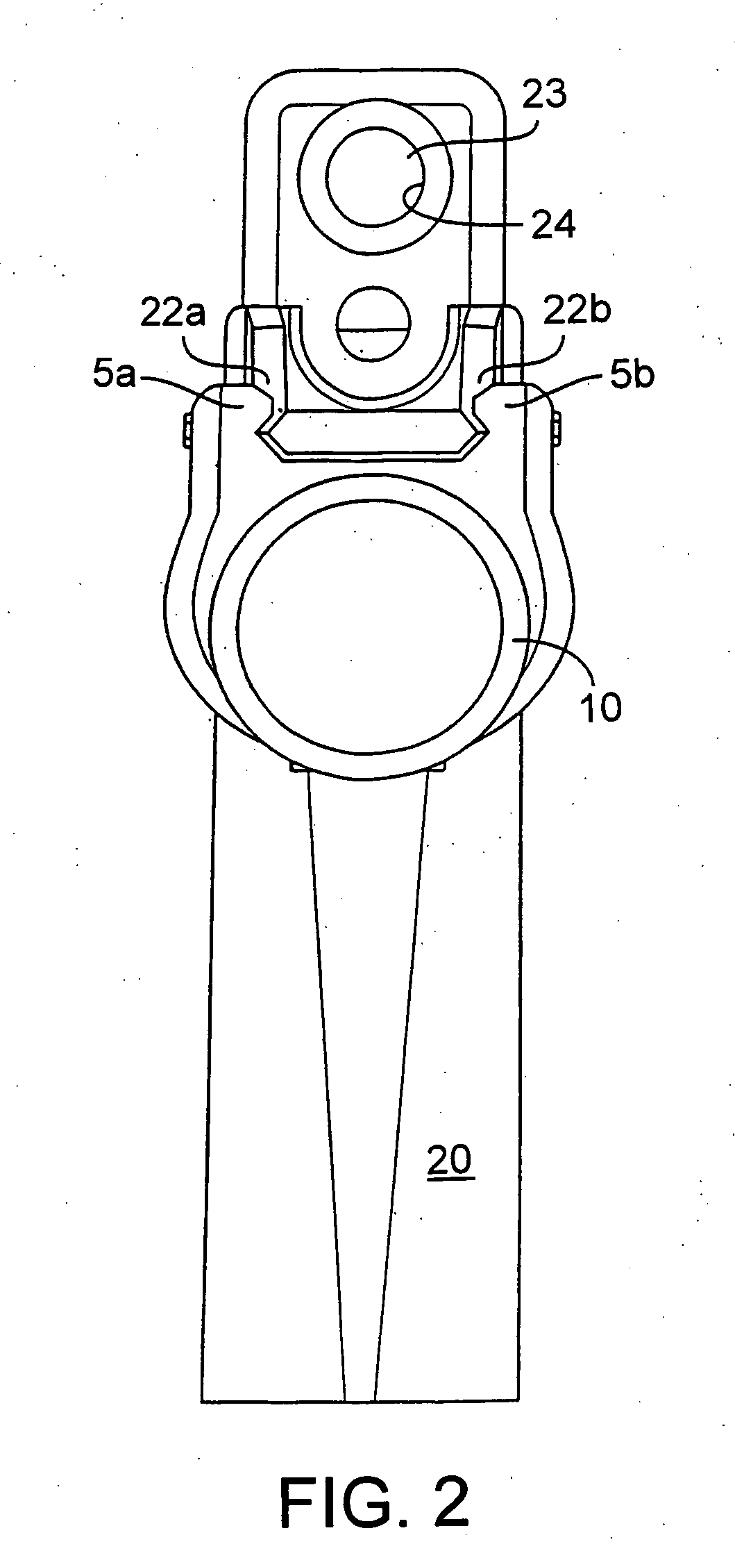
[0054] With reference to FIGS. 1, 2 and 4, there is depicted an auxiliary device 10 mounted to a pistol-type weapon 20. For convenience, the description that follows refers to the auxiliary device as an illuminator, which is a device generally used to cast light upon a target area or a portion thereof. This should not be construed as a limitation of the invention, however, as this embodiment is for illustrative purposes only. As those skilled in the art will appreciate from this disclosure, the novel features described herein may readily be applied to other auxiliary devices and weapons. Moreover, the figures are provided as examples only. It is to be understood that the invention is not limited to the particulars depicted in the figures.

[0055] According to one embodiment, weapon 20 comprises a weapon frame 21 with rails or grooves 22a and 22b, located in and extending along at least a portion of the weapon frame 21, preferably parallel with an axis 23 of the barrel 24. Preferably,...


PUM


Abstract

An attachment system is provided for attaching an auxiliary device to a weapon having a frame, and in particular to a weapon frame in the area forward of the trigger guard. An attachment mechanism on the auxiliary apparatus is adapted to be engageable with a rail on the weapon to selectively attach the auxiliary apparatus. The weapon may include a transverse slot which can be engaged by a portion of the auxiliary device to prevent the auxiliary apparatus from sliding relative to the weapon due to recoil forces associated with firing the weapon.

Description

CROSS-REFERENCE TO RELATED APPLICATIONS [0001] This application is a continuation-in-part of and claims priority to co-pending U.S. application Ser. No. 10 / 408,762, filed Apr. 7, 2003, which is a continuation application of U.S. application Ser. No. 09 / 706,085 filed Nov. 3, 2000, now U.S. Pat. No. 6,574,901, which is a continuation application of Ser. No. 09 / 109,048, filed Jul. 2, 1998, now U.S. Pat. No. 6,185,854, both entitled “Auxiliary Device for a Weapon and Attachment Thereof” which are hereby incorporated by reference in their entirety.TECHNICAL FIELD [0002] The invention relates generally to an auxiliary (e.g., illumination) device for a weapon and, more particularly, to attaching an auxiliary device to a weapon. BACKGROUND [0003] The need to be able to effectively see a target and aim a weapon in the direction of the target is well recognized. Auxiliary devices to facilitate illuminating a target or aiming a weapon, especially under low light conditions, are known. Examples...

Claims


Application Information

Patent Timeline
Patent Type & Authority Applications(United States)
IPC IPC(8): F41A19/00
CPCF41G11/003
Inventor SOLINSKY, KENNETH S.WOODMAN, WALLACE E. IIIHOWE, ALAN T.
Owner L 3 COMM INSIGHT TECH
Why Eureka
Try Eureka