Noise reducing equipment

Inactive Publication Date: 2005-11-24
YANO HIROSHI +1
View PDF6 Cites 23 Cited by
  • Summary
  • Abstract
  • Description
  • Claims
  • Application Information

AI Technical Summary

Benefits of technology

[0004] Noise reducing equipment has been discovered in accordance with the present invention for attachment to a sound barrier wall that is at least as effective in reducing noise as compared to the equipment disclosed in the aforementioned Japanese patent publication. The noise reducing equipment of the present invention comprises an assembly composed of a predetermined number of interconnected resonant chambers mounted in tandem and connected to said sound

Problems solved by technology

P3485552 is effective for reducing noise the construction and installation requirements to form a substantially uniform arrangement of an equa

Method used


Image

  • Noise reducing equipment
  • Noise reducing equipment
  • Noise reducing equipment

Examples


Example

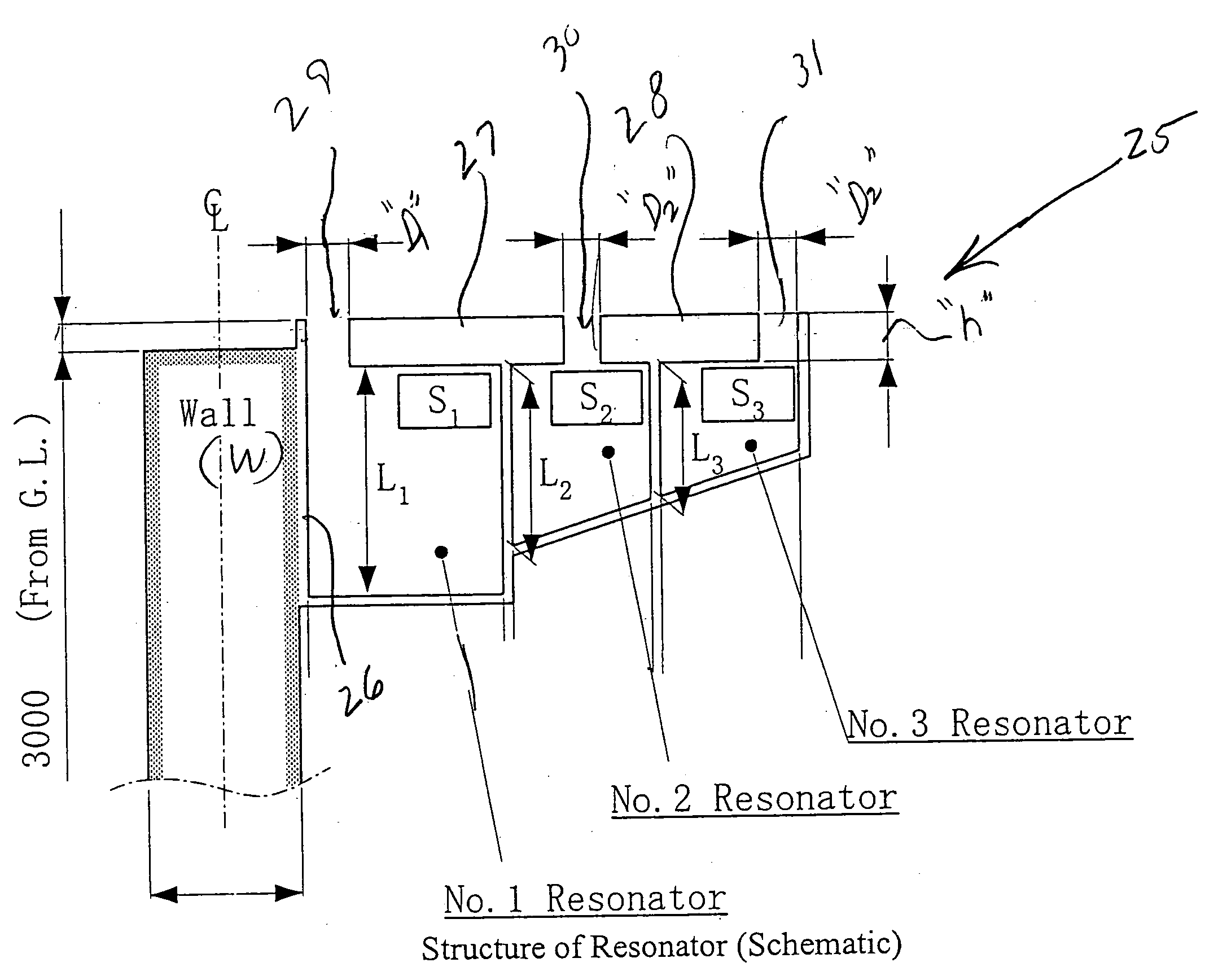
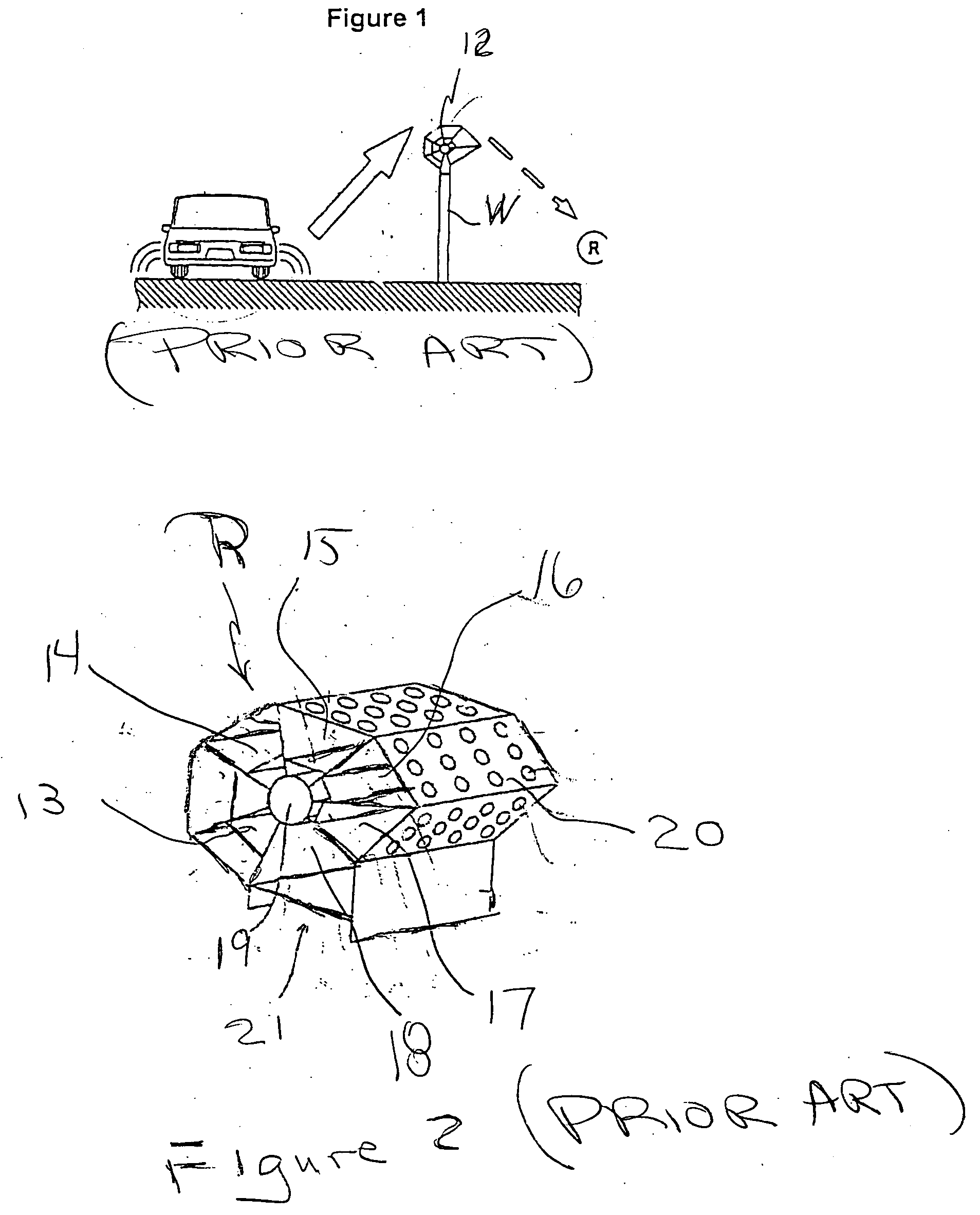
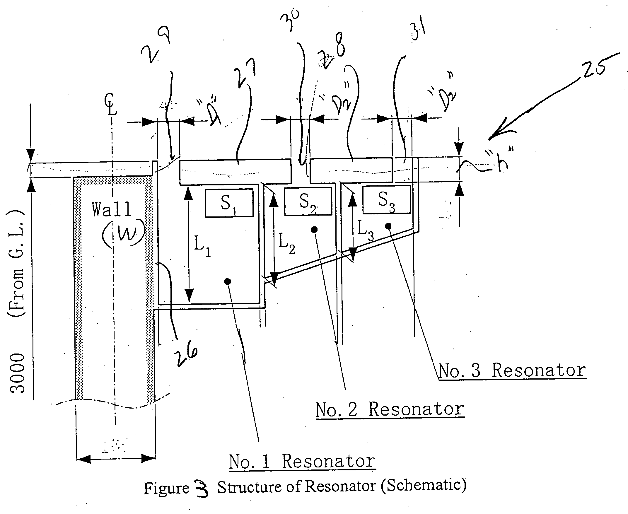
[0016] A prior art configuration of noise reducing equipment for traffic noise is shown in FIG. 1 and corresponds to that described in Japanese Patent No. P3485552. FIG. 2 is an enlarged isometric view of the prior art assembly of resonant chambers in the noise reducing equipment of FIG. 1.

[0017] The sound barrier wall W is constructed of, for example, concrete and is vertically erected to form a partition between a source of sound such as traffic noise generated from passing automobiles on one side of the vertically oriented sound barrier wall W and an observation point R located on the opposite side of the wall W. A resonator 12, representing an assembly of resonant chambers is mounted on the vertical top end of the sound barrier wall with the resonant chambers arranged to be substantially symmetrically disposed on each opposite side of the sound barrier wall so as to uniformly inhibit the propagation of sound waves at the wall. The propagation of sound waves from a sound source ...


PUM


Abstract

The noise reducing equipment of the present invention is used in combination with a vertically oriented sound barrier wall to reduce the level of noise from a source of sound such as traffic generated on one side of the sound barrier wall and comprises an assembly composed of a predetermined number of interconnected resonant chambers mounted in tandem to a sound barrier wall such that the assembly of resonant chambers extends from the sound barrier wall on only the side thereof opposite the source of generated sound and at a location adjacent the top end thereof with each of the resonant chambers having a plurality of walls defining separate volumetric areas with the resonant chamber closest to the sound barrier wall having a volumetric area larger than the volumetric area of each of the other resonant chambers. The noise reducing equipment should also include a plurality of sections composed of sound absorption material in an arrangement with each section extending between adjacent resonant chambers and being laterally spaced apart from one another to form an opening to each resonant chamber.

Description

FIELD OF INVENTION [0001] This invention relates to the field of sound abatement and more particularly to noise reducing equipment for use in combination with a sound barrier such as a wall for reducing the level of noise particularly from traffic sounds. BACKGROUND OF THE INVENTION [0002] It is known to use a sound barrier wall for reducing and impeding the transmission of sound waves. A sound barrier wall can, for example, be installed alongside an expressway to confine and minimize traffic noise generated by passing automobiles. It is also known to add resonance equipment on top of a sound barrier wall which includes several different type of Helmholtz resonators responsive to selected resonance frequencies of the source of noise to be abated so as to more effectively minimize the noise level at the barrier wall and confine the level of noise to an acceptable level. An arrangement consisting of a combination of a sound barrier wall and resonance equipment is disclosed in Japanese...

Claims


Application Information

Patent Timeline
IPC IPC(8): B64F1/26E01F8/00E04H17/00F01N1/02F01N1/24F01N13/18G10K11/00G10K11/172
CPCB64F1/26E01F8/0005E01F8/0094G10K11/172F01N1/04F01N1/24F01N2490/155F01N1/02
Inventor YANO, HIROSHIODA, MITSUAKI
Owner YANO HIROSHI
Why Eureka
Try Eureka