Substrate heating device

a heating device and substrate technology, applied in the direction of hot plate heating arrangement, light and heating apparatus, cycles, etc., can solve the problems of difficult to precisely control the temperature of the respective zone, using the thinnest available wire,

Active Publication Date: 2005-11-24
NGK INSULATORS LTD
View PDF7 Cites 80 Cited by
  • Summary
  • Abstract
  • Description
  • Claims
  • Application Information

AI Technical Summary

Benefits of technology

[0010] An object of the present invention is to provide a substrate heating device including resistance heating elements for the respective zones into which a heating surface is divided, which can prevent influences of lead wires and precisely control temperature for respective zones.
[0012] According to such a substrate heating device, the lead wires connected to respective terminals of the resistance heating elements are not buried in the ceramic base plate and are wired on an outer surface of the ceramic base plate other than the heating surface, in the substrate heating device having resistance heating elements for the respective zones into which the heating surface is divided. Therefore, the substrate heating device can prevent influences of lead wires and precisely control temperature for respective zones.

Problems solved by technology

Meanwhile, in this case, since the buried lead wires themselves may become defects of the ceramic base plate, the thinnest available wire must be used as lead wires to prevent s generating tress.
Therefore, it is difficult to precisely control the temperatures of the respective zones due to influence of heat generation of the lead wires.

Method used


Image

  • Substrate heating device
  • Substrate heating device
  • Substrate heating device

Examples


first embodiment

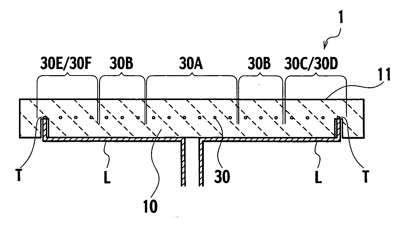
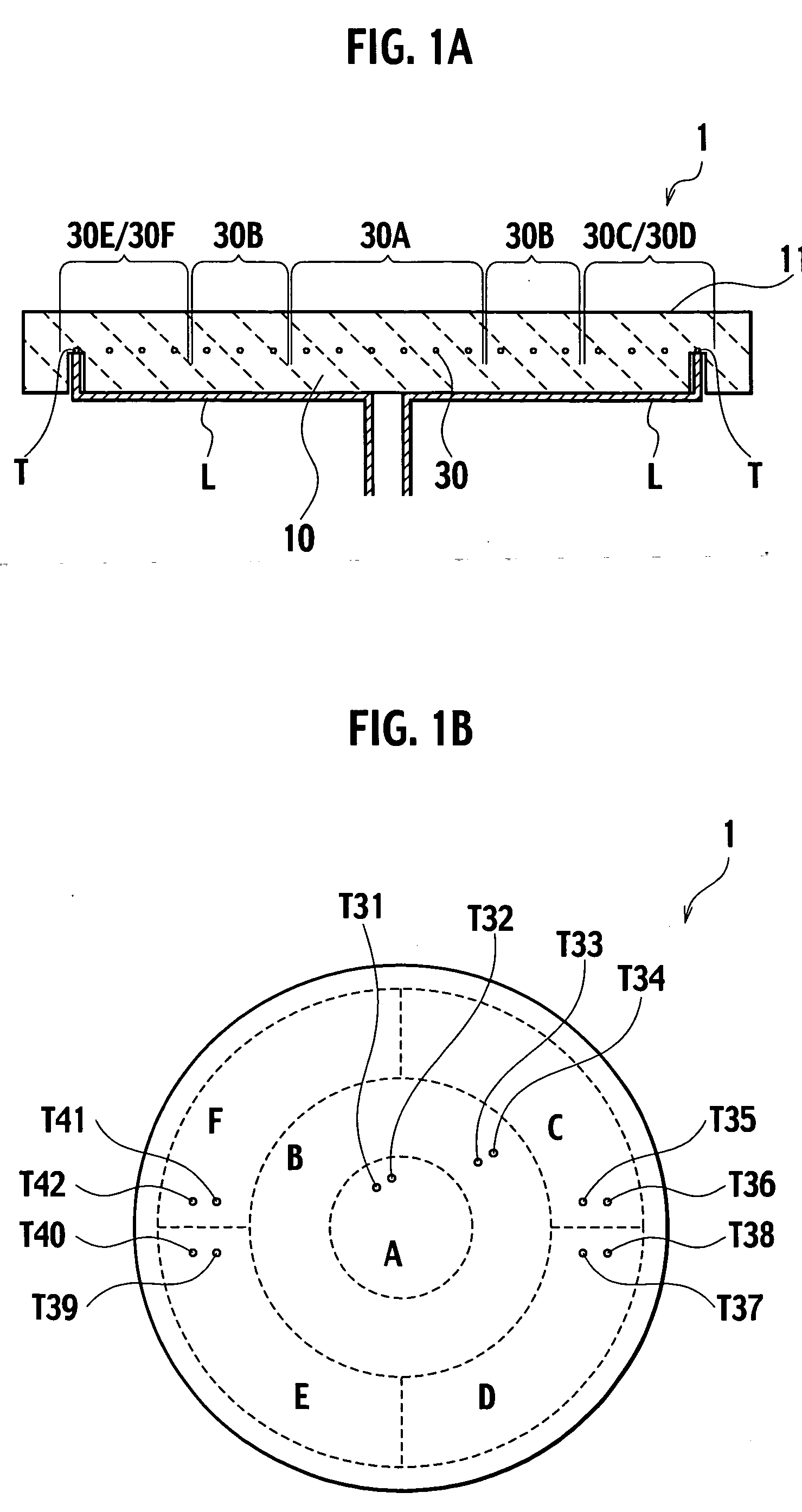
[0021] A substrate heating device, according to a first embodiment of the present invention, is a ceramic heater including resistance heating elements buried in a ceramic base plate. More specifically, it is a multi-zone heater with independent resistance heating elements buried in respective zones into which a heating surface is divided. A substrate is placed on the heating surface. Lead wires connected to respective terminals of the resistance heating elements are not buried in the ceramic base plate, and are wired on an outer surface of the ceramic base plate other than the heating surface.

[0022]FIG. 1A is a sectional view of the substrate heating device 1, according to the first embodiment of the present invention. FIG. 1B is a plan view showing an example of the heating surface having divided multiple zones. Note that through-holes for lift pins or the like are not shown in the drawing for convenience; however, those are formed as needed.

[0023] As shown in FIG. 1A, the substr...

second embodiment

[0046]FIG. 3 shows a sectional view of a substrate heating device 2, according to a second embodiment of the present invention. The substrate heating device 2, according to the second embodiment of the present invention, includes an auxiliary plate 60, which is an isolating auxiliary member, on the underside, i.e., the opposite surface to the heating surface 11 of the ceramic base plate 10 of the substrate heating device 1 shown in FIG. 1. The structure thereof other than the auxiliary plate 60 is almost the same as that of the substrate heating device 1 shown in FIG. 1. In other words, the substrate heating device 2 is a multi-zone heater in which multiple resistance heating elements 30 are buried. Lead wires L connected to terminals T of the respective heating resisters are not buried in the ceramic 10, and are wired on the underside thereof instead. The auxiliary plate 60 is provided on the underside of the ceramic base plate 10, so as to cover the lead wires L.

[0047]FIG. 4A is ...

third embodiment

[0060]FIG. 6 shows a sectional view of a substrate heating device 3a, according to a third embodiment of the present invention. The substrate heating device 3a, according to the third embodiment of the present invention, includes a tubular member 80 on the underside of the ceramic base plate 10 (i.e., the opposite surface to the heating surface 11) in the substrate heating device shown in FIG. 3. The structure thereof other than the tubular member 80 is the same as that of the substrate heating device 2. In other words, the substrate heating device 3a is a multi-zone heater in which multiple resistance heating elements 30 are buried. In addition, lead wires L connected to terminals of the respective resistance heating elements 30 are wired on the underside of the ceramic base plate 10. Furthermore, the auxiliary plate 60 is provided on the underside of the ceramic base plate 10.

[0061] The tubular member 80 houses part of lead wires L and power supply member such as a power supply l...


PUM

PropertyMeasurementUnit
diameteraaaaaaaaaa
temperatureaaaaaaaaaa
pressureaaaaaaaaaa

Abstract

A substrate heating device comprises a ceramic base plate having a heating surface on which a substrate is placed, resistance heating elements buried in the ceramic base plate for respective zones into which the heating surface is divided, terminals connected to the resistance heating elements respectively, and lead wires connected to the terminals respectively and wired on an outer surface of the ceramic base plate other than the heating surface.

Description

CROSS REFERENCE TO RELATED APPLICATIONS [0001] This application is based upon and claims the benefit of priority from prior Japanese Patent Application No. 2004-117237, filed on Apr. 12, 2004; the entire contents of which are incorporated herein by reference. BACKGROUND OF THE INVENTION [0002] 1. Field of the Invention [0003] The present invention relates to a substrate heating device, which heats a substrate such as a semiconductor substrate, a liquid crystal substrate or the like. More specifically, the present invention relates to a substrate heating device which includes a ceramic base plate and resistance heating elements buried in the ceramic base plate. [0004] 2. Description of the Related Art [0005] A ceramic heater which has a ceramic base plate and resistance heating elements buried in the ceramic base plate is widely used as a substrate heating device in a semiconductor manufacturing process or the like. The ceramic heater used in a semiconductor manufacturing process or ...

Claims


Application Information

Patent Timeline
Patent Type & Authority Applications(United States)
IPC IPC(8): H05B3/20F23Q7/22H01L21/00H01L21/02H01L21/68H01L21/683H05B3/02H05B3/10H05B3/12H05B3/74
CPCH01L21/67103A63G25/00B62K17/00
Inventor GOTO, YOSHINOBUTSURUTA, HIDEYOSHI
Owner NGK INSULATORS LTD
Why Eureka
Try Eureka