Oil drain valve

a drain valve and oil technology, applied in the field of drain plugs, can solve the problems of easy loss or misplacement of drain plugs, and achieve the effect of convenient grip

Inactive Publication Date: 2005-11-24
ILLINOIS TOOL WORKS INC
View PDF20 Cites 14 Cited by
  • Summary
  • Abstract
  • Description
  • Claims
  • Application Information

AI Technical Summary

Benefits of technology

[0005] The present invention is directed to a drain valve that may be used in numerous applications, including small gas engines. The drain valve of the invention includes several embodiments and generally may include a valve body, an o-ring, and a cap. The disclosed drain valve eliminates the need for a tool, such as a wrench, to drain the fluid from the engine. The dra...

Problems solved by technology

As a loose item, the removed drain plug is prone to being lost or misplaced.
Occasionally, during the replacement of the plug, the mating thread...

Method used


Image

  • Oil drain valve
  • Oil drain valve
  • Oil drain valve

Examples


Embodiment Construction

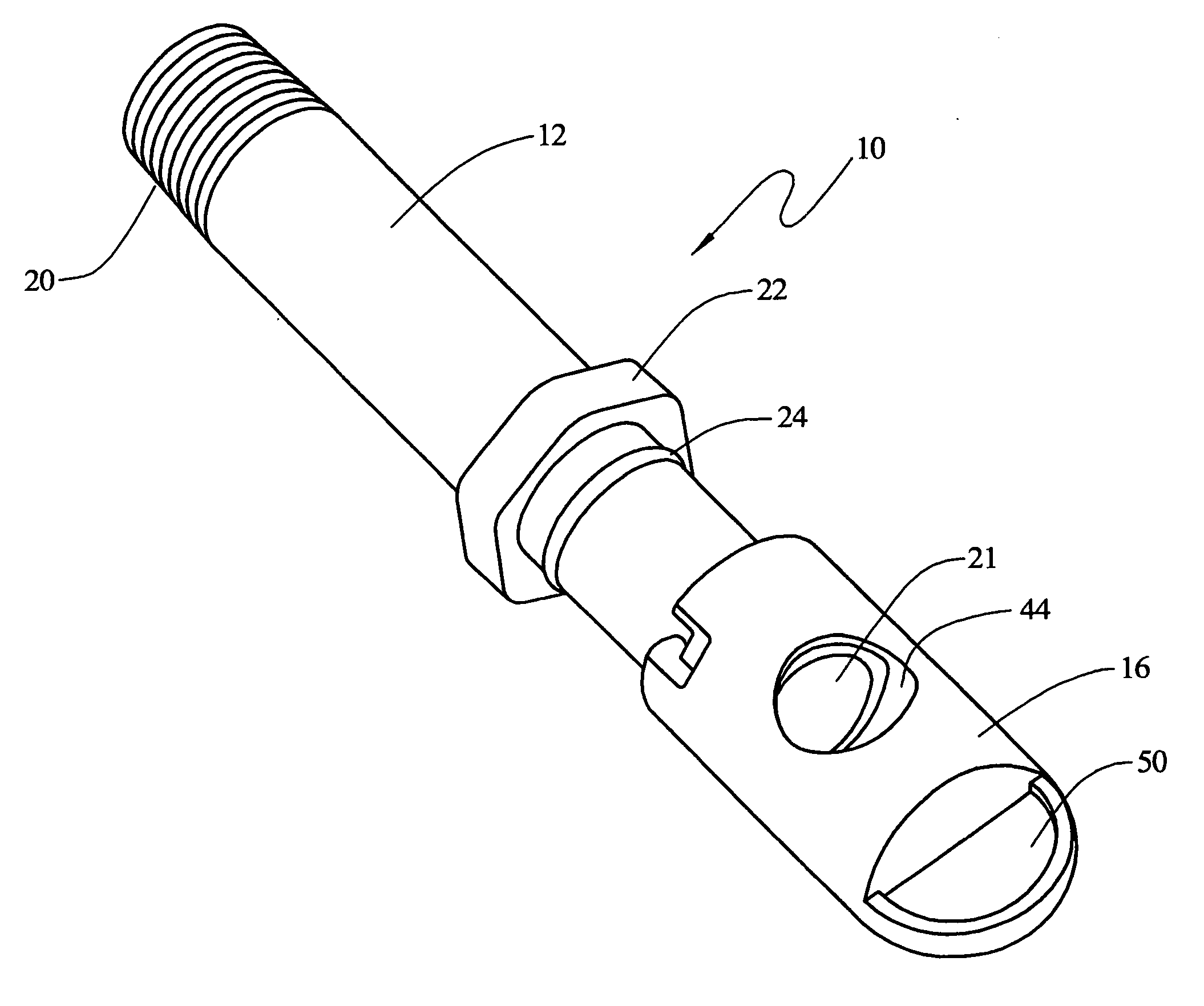
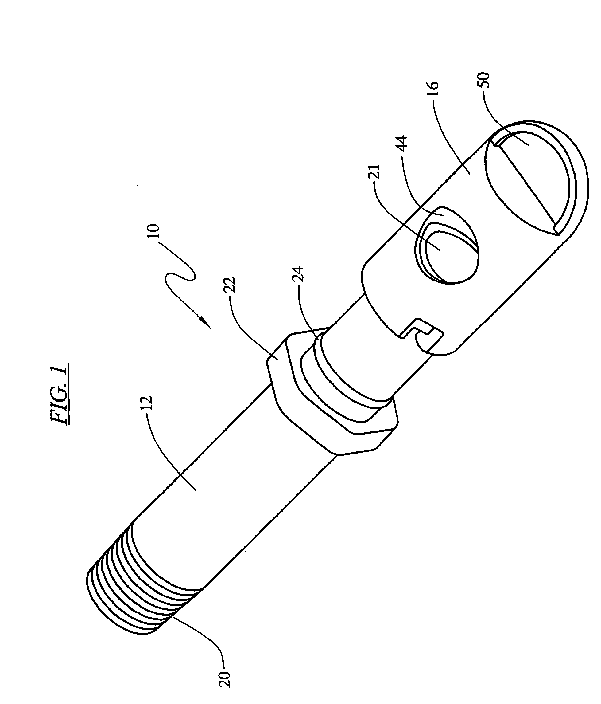
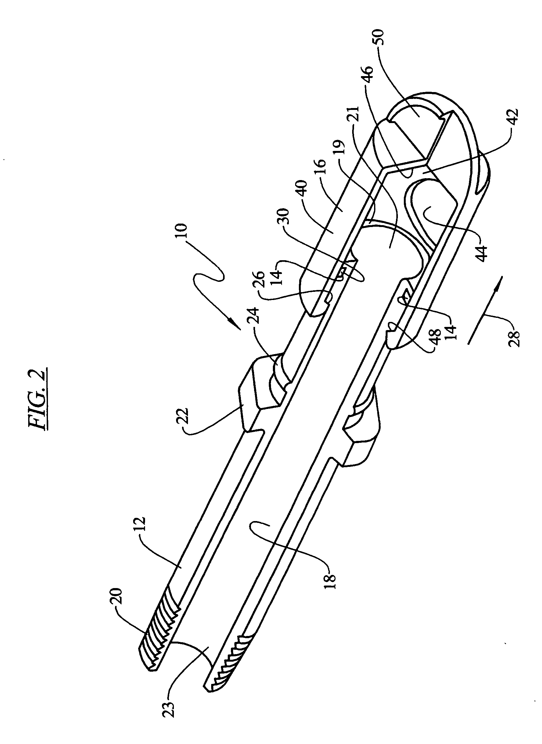
[0017] Referring to the figures there are depicted exemplary embodiments of a drain valve of the present invention. Referring to FIGS. 1-3, there is illustrated an exemplary drain valve 10 for use with an engine, such as small gasoline engine. One skilled in the art will appreciate that the teachings of the present invention may be used with numerous other drain applications in addition to the exemplary applications described herein.

[0018] In one embodiment, the exemplary drain valve 10 is a three piece assembly that includes a valve body 12, an o-ring 14, and a cap 16. Referring to FIG. 2, the valve body 12 is generally cylindrical in shape and defines an interior cylindrical passageway 18 extending the length of the body. The valve body 12 also defines a first end 19 having an opening 21 and a second opposing threaded end 20 also having an opening 23. The threaded end 20 is sized to mate with a threaded opening in the engine sump or crankcase, not shown. Positioned on the exterio...


PUM


Abstract

A drain valve to be used with numerous drain applications, such as draining fluid from an engine, includes in an exemplary embodiment a valve body, an o-ring and a cap. In another exemplary embodiment, the drain valve includes a valve body, an o-ring, a cap retainer and a cap. The drain valve eliminates the need for a tool, such as a wrench, to drain the fluid from the engine, for example. The drain valve includes a push-pull or a twist-and-pull cap feature to manipulate the valve; however, the drain cap remains on the drain valve and therefore cannot be lost or misplaced. Moreover, the drain valve includes a drain cap that is rotatable to direct the fluid flow out the valve and also provides an easy grip for opening and closing the valve.

Description

CROSS REFERENCE TO RELATED APPLICATION [0001] This Non-Provisional Application claims benefit to U.S. Provisional Application Ser. No. 60 / 573,960 filed May 24, 2004.FIELD OF THE INVENTION [0002] The present invention relates generally to drain plugs, and more particularly, to drain valves for a small gas engine. BACKGROUND OF THE INVENTION [0003] It is known that drain plugs are installed on small engines typically below the oil sump of the engine and used as a removable plug to permit the fluid in the sump to be drained and replaced. The known drain plugs conventionally include at one end a threaded portion that mates with a threaded opening in the oil sump. At the opposite end, the known drain plugs include a tool interface, such as a hexagonal shaped head, that, with the aid of a tool, such as a wrench, is used to install the drain plug. [0004] The known drain plugs, however, have several drawbacks. For example, the known drain plugs must be removed from the oil sump before the o...

Claims


Application Information

Patent Timeline
IPC IPC(8): F16K24/04F16K31/00F16K35/02
CPCF16K35/027F16K24/04
Inventor PLIML, FRANK V. JR.
Owner ILLINOIS TOOL WORKS INC
Why Eureka
Try Eureka