Passenger cabin seat power bus

a passenger cabin and power bus technology, applied in the direction of movable seats, seating arrangements, pedestrian/occupant safety arrangements, etc., can solve the problems of increasing the complexity of the operation and the amount of time required to install seats, and the process is cumbersome and time-consuming, and the rewiring of aircraft is a costly and time-consuming process

Inactive Publication Date: 2005-11-24
THE BOEING CO
View PDF10 Cites 69 Cited by
  • Summary
  • Abstract
  • Description
  • Claims
  • Application Information

AI Technical Summary

Benefits of technology

[0007] A power bus device and method operable to distribute power / data to a plurality of seats. In one embodiment, the power bus delivers power / data to any number of select locations within a mobile platform. Power and / or data is transmitted between the power bus and a plurality of passenger seats, via a connector, at any point along the power bus, thus eliminating the need to run separate connections between the power and / or data source and each seat.

Problems solved by technology

Taking care to avoid the exposed wires increases both the complexity of the operation and the amount of time required to install the seats.
This process is cumbersome and time consuming.
As would be expected, re-wiring an aircraft is a costly and time consuming process.

Method used


Image

  • Passenger cabin seat power bus
  • Passenger cabin seat power bus
  • Passenger cabin seat power bus

Examples


Embodiment Construction

[0044] The following description of the preferred embodiments is merely exemplary in nature and is in no way intended to limit the invention, its application, or uses.

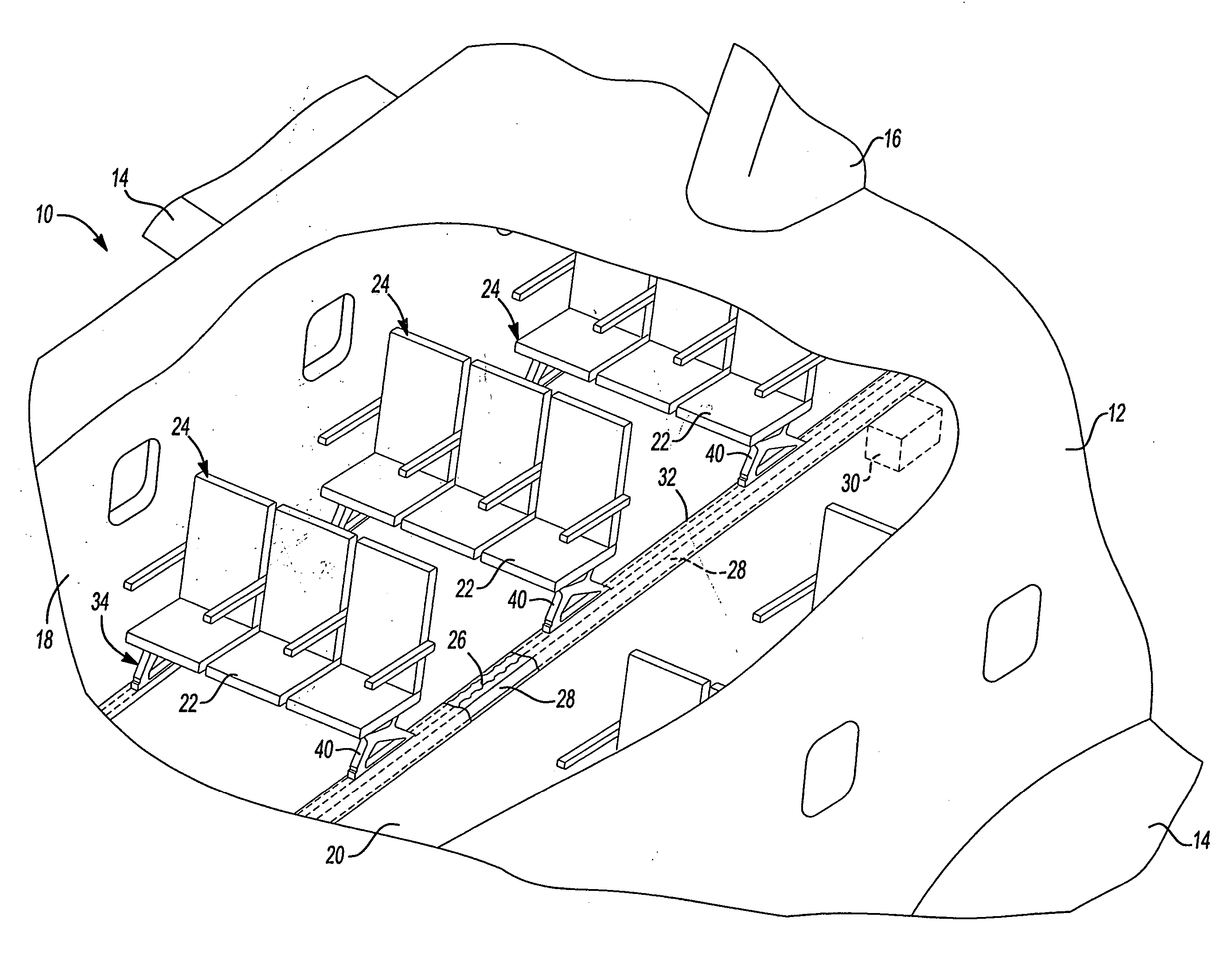
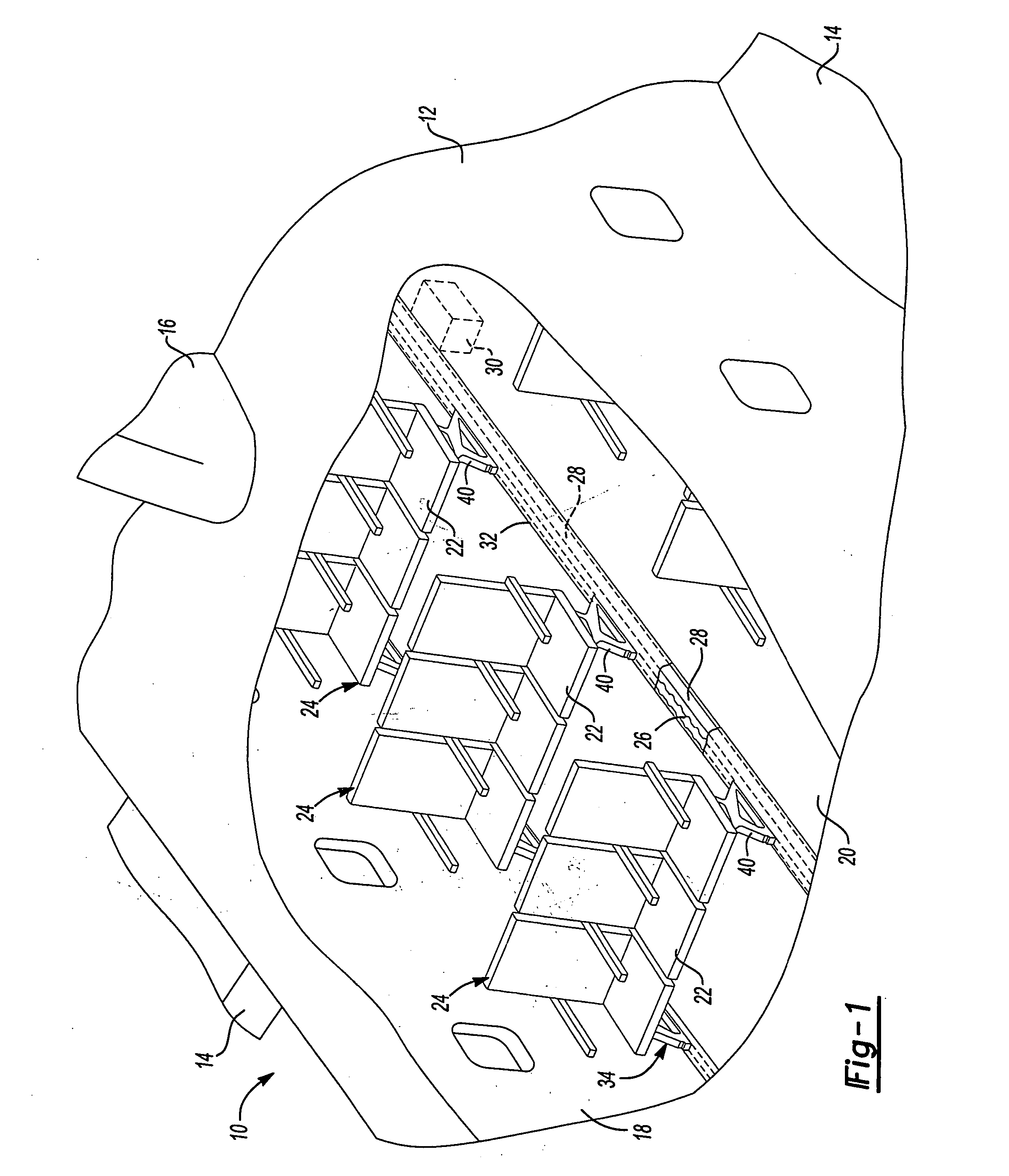
[0045] With initial reference to FIG. 1, a passenger aircraft equipped with a power bus system according to one preferred embodiment of the present invention is illustrated at reference numeral 10. It will be appreciated immediately, however, that the present invention can be implemented in virtually any form of mobile platform, such as a ship, train, bus, rotor craft or other airborne vehicle, or even in fixed structures such as theatres, conference rooms, auditoriums, etc., or whenever there is a need to supply power and / or data signals to connection ports or components on a plurality of seats or any other location. For example, the system could be used for overhead lighting and passenger controls in an aircraft passenger cabin.

[0046] The aircraft 10 generally includes a fuselage 12, wings 14, and a tail fin 16. Th...


PUM


Abstract

A conductive bus device and method operable to distribute signals throughout a platform. The bus delivers signals to any number of select locations within the platform, such as to seats mounted to a seat track. The bus is mounted beneath a floor of the platform. The signals can be transmitted between the power bus and the passenger seats using a conductor that extends from the passenger seats to the bus through a opening in the seat track. The bus device and method eliminates the need to run separate connections between a signal source and each seat. This device and method significantly reduce the cost, energy, and time necessary to wire each seat individually.

Description

CROSS-REFERENCE TO RELATED APPLICATIONS [0001] This application claims the benefit of U.S. provisional application Ser. No. 60 / 556,826 filed on Mar. 27, 2004, which is incorporated herein by reference. [0002] The following applications are also incorporated by reference herein: provisional application Ser. No. 60 / 557,044 filed on Mar. 27, 2004; provisional application Ser. No. 60 / 556,823 filed on Mar. 27, 2004; provisional application Ser. No. 60 / 556,747 filed on Mar. 27, 2004; provisional application Ser. No. 60 / 556,748, filed on Mar. 27, 2004; U.S. application Ser. No. 10 / 810,324 filed on Mar. 27, 2004; U.S. application Ser. No. 10 / 898,729 filed on Jul. 23, 2004; U.S. application Ser. No. 10 / 936,004 filed on Sep. 8, 2004; U.S. application Ser. No. 10 / 983,906 filed on Nov. 8, 2004; and U.S. application Ser. No. 10 / 943,035 filed on Sep. 16, 2004.FIELD OF THE INVENTION [0003] The present invention relates to mobile platform electronic systems. In particular, the present invention rel...

Claims


Application Information

Patent Timeline
Patent Type & Authority Applications(United States)
IPC IPC(8): B60N2/02B60N2/42
CPCB60N2/0224B64C1/20B64D11/0624B60N2002/0264B64D11/06B60N2/0264B64D11/0696
Inventor MITCHELL, BRADLEY J.CALLAHAN, KEVIN S.LAIB, TREVOR M.JOHNSON, ROBERT T.SANTALA, DARRELL E.
Owner THE BOEING CO
Why Eureka
Try Eureka