
Optical system

Inactive Publication Date: 2005-11-24
OLYMPUS CORP
View PDF3 Cites 4 Cited by
  • Summary
  • Abstract
  • Description
  • Claims
  • Application Information

AI Technical Summary

Benefits of technology

[0014] An object of the present invention is to provide an optical system which has a simple composition and is capable of preventing image blur within a visual field through a finer from being blurred.

Problems solved by technology

When the camera shake correction lens component is decentered, imaging performance is degraded by aberrations produced due to the decentering.
Furthermore, distortion produced by the eccentricity makes an image asymmetrical with regard to an optical axis.
In addition, when the camera shake correction lens component has a large weight, this lens component constitutes a heavy burden which is imposed on an actuator which is used for moving the camera shake correction lens component.
When a camera shake sensitivity is high, in contrast, it is difficult to control a movement of the camera shake correction lens component.

Method used


Image

  • Optical system
  • Optical system
  • Optical system

Examples


embodiment 1

Δα=0.93° (Embodiment 1)

Δα=0.03° (Embodiment 2)

β=1.19

[0187] As apparent from the values listed above, the third and fourth embodiments satisfy all of the conditions (1) through (8).

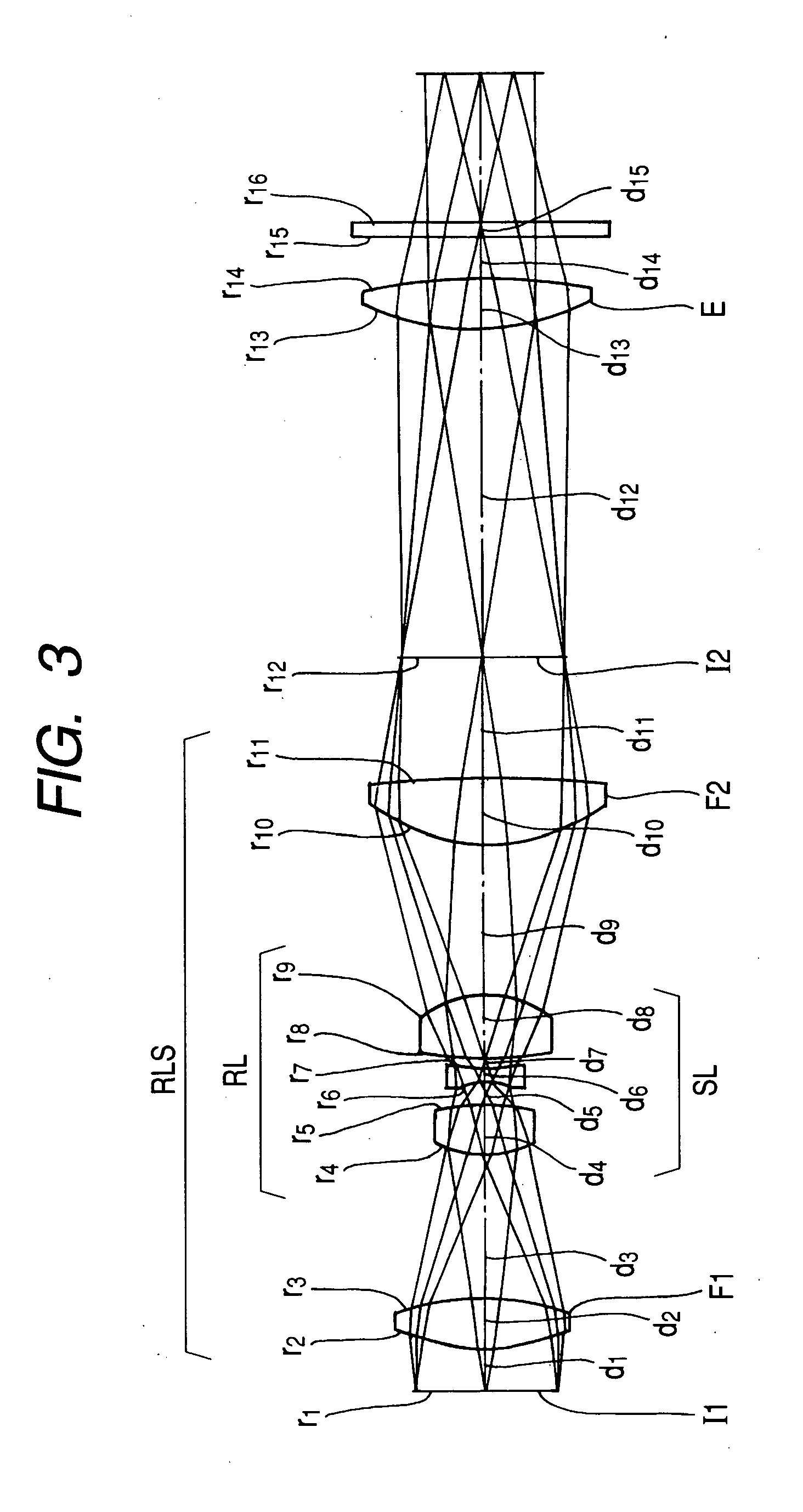
[0188] In these embodiments, an effective diameter of a relay lens component and the like are as listed below: [0189] Effective diameter of relay lens component=8.4 mm [0190] Maximum effective diameter of finder optical system=15.5 mm [0191] Effective diameter of relay lens component / maximum effective diameter of finder optical system=0.54

[0192] Furthermore, used in these embodiments are rotationally symmetrical aspherical surfaces as an object side surface (r2) of the first field lens F1, an object side surface (r10) of the second field lens and an object side surface (r13) of the eyepiece E.

[0193] The aspherical surfaces are expressed by the following formula; z=ch2 / [1+{1-(1+k)⁢c2⁢h2}1 / 2]+Ah4+Bh6+Ch8+Dh10+…[0194] wherein a reference symbol h represents a distance as measured from an optical axis (h...


PUM


Abstract

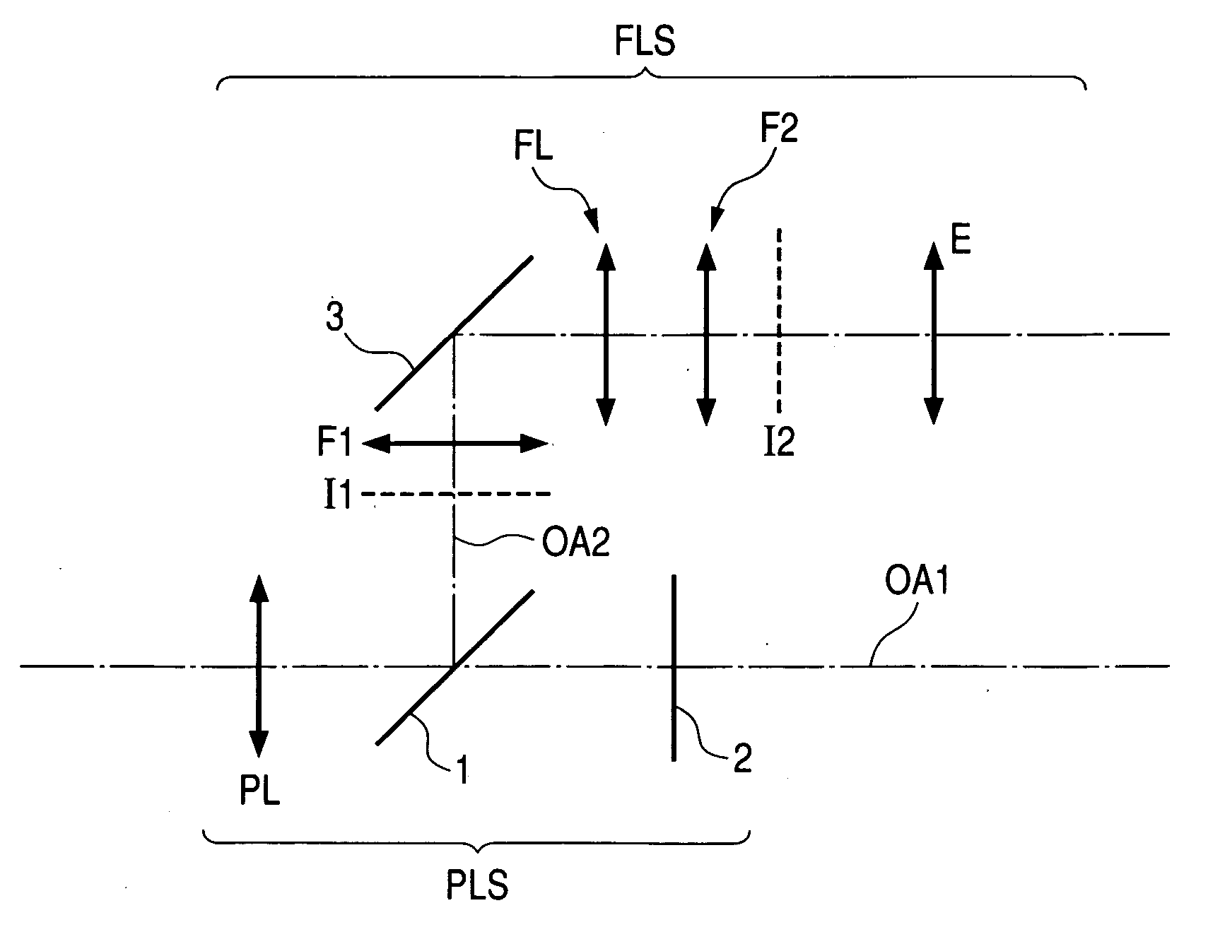
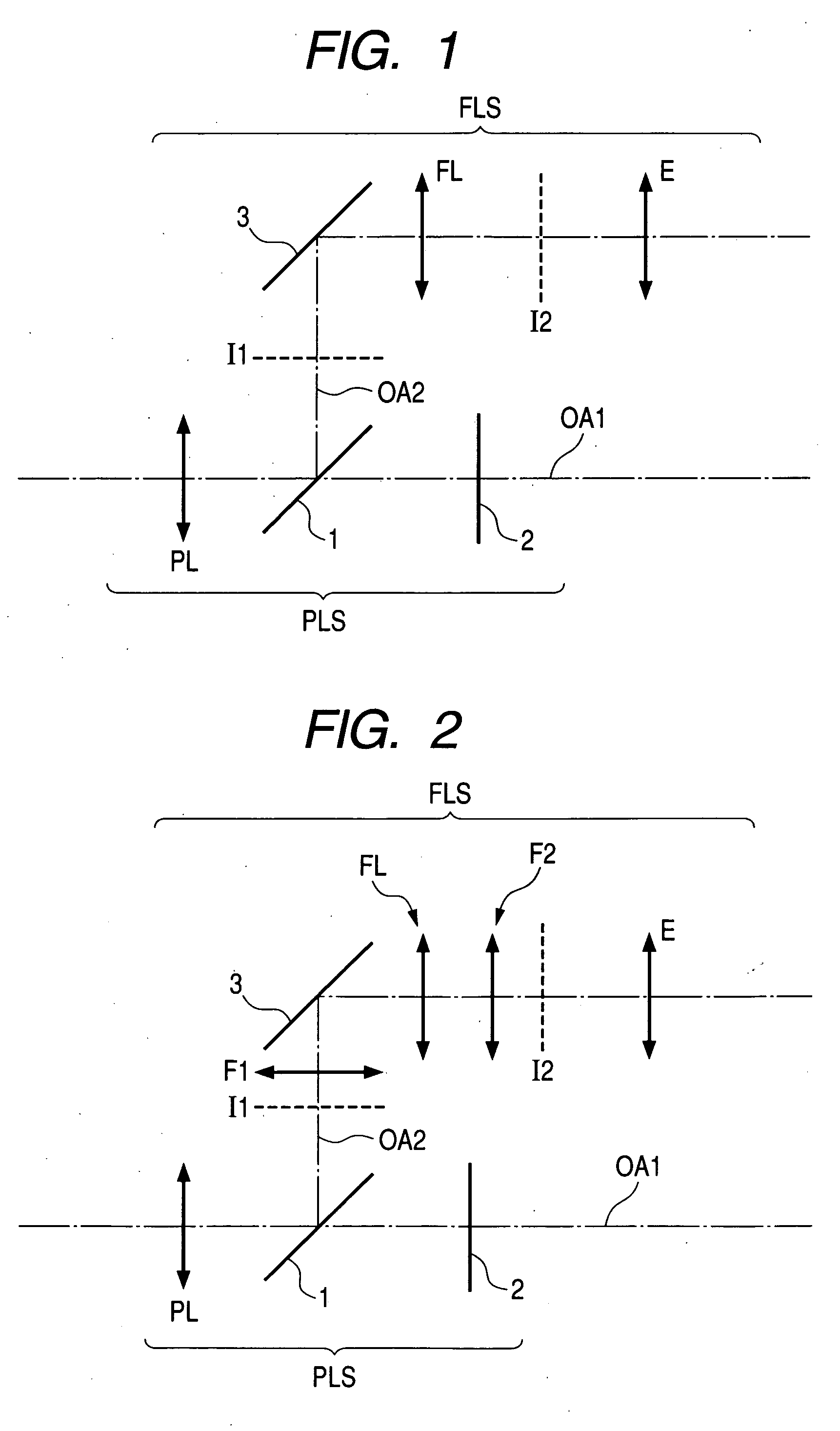
An optical system comprising a photographing optical system, a finder optical system and optical path changing means for changing an optical path from the photographing optical system to the finder optical system or an optical system for observing an image of an object after rays from an object to be photographed are reflected twice or more times comprising camera shake correction means disposed in a finder optical system.

Description

BACKGROUND OF THE INVENTION [0001] a) Field of the Invention [0002] The present Invention relates to an optical system. Concretely, the present invention relates to an optical system which has a function to prevent an image from being blurred due to a camera shake, for example, a shake caused in particular at a time of photographing with a camera held by hands, and more specifically a finder for a photographing apparatus such as a digital camera, a film camera, a video camera or the like. [0003] b) Description of the Prior Art [0004] Known as conventional examples of finder optical system which has a camera shake correction function are those which are described in the following literatures: [0005] Japanese Patent Kokai Application No. Hei 9-329820 [0006] Japanese Patent Kokai Application No. 2003-91027 [0007] Out of these conventional examples, a finder optical system which is described In Japanese Patent Kokai Application No. Hei 9-329820 has a composition shown In FIG. 32. [0008]...

Claims


Application Information

Patent Timeline
IPC IPC(8): G02B27/64G03B13/06G03B13/14G03B17/02H04N5/228
CPCG02B27/646G03B17/02G03B13/14G03B13/06
Inventor KEIICHI, KUBA
Owner OLYMPUS CORP
Learn More