Battery rack and system

a battery rack and rack system technology, applied in the field of racks, can solve the problems of reducing the capacity reducing the service life of the battery rack, so as to facilitate the vertical air flow, reduce the cost of installation, and facilitate the effect of vertical air flow

Inactive Publication Date: 2005-11-24
KIM MFG
View PDF30 Cites 18 Cited by
  • Summary
  • Abstract
  • Description
  • Claims
  • Application Information

AI Technical Summary

Benefits of technology

[0014] A still another object of the present invention is to provide a battery rack assembly and systems wherein the frame including a novel configuration of end frame members which are symmetrical and therefore can be manufactured economically and installed easily and which are characterized by a series of ventilation slots and webs between the slots which confront a plurality of open compartments in the rack for the batteries to thereby aid and guide the batteries into the rows defined in the compartments.
[0015] Still another object of the present invention is to provide a novel battery rack assembly and system which has great flexibility and only one designed frame is needed for the entire 120-size system product line in a 8-high configuration.
[0016] Still a further object of the present invention is to provide a novel battery rack assembly and system wherein the shelves are divided into rows or zones for the batteries defined by a series of spaced dimples and openings spacing the rows of batteries at a predetermined distance from one another to whereby the ventilation slots facilitate vertical air flow over the batteries and with again the result of improving battery performance.
[0017] Still another object of the present invention is to provide a novel jacket configuration for the batteries characterized by a unique design allowing for handling the cells individually thereby facilitate handling and wherein the open end configuration is such to protect the joint between the cover and the jar from damage.
[0018] Still another object of the present invention is to provide a jacket configuration where the cell need not be extracted from the jacket or handled by its posts and thereby eliminating cell posts seal damage and jar damage as well as diminished capacity due to loss of pressure characteristic of prior art configuration.
[0019] A still further object of the present invention is to provide a novel jacket arrangement constructed of two identical pieces which are configured to be easily welded together to form a neat compact jacket for the individual batteries which includes points for picking up and handling the batteries and therefore eliminates cell damage.

Problems solved by technology

It has been found that without compression, these batteries tend to bulge thereby diminishing capacity.
These prior systems have certain disadvantages and draw backs.
These trays are therefore rather bulky and difficult to handle at the installation site.
Further, the module pockets, in some instances, are oversized relative to the battery and require the use of shims to snugly position the batteries in the module pockets.
Accordingly, when the batteries swell, if there is need for the installer to remove the batteries, the batteries are usually gripped by the posts which can cause battery damage.
Further, it has been found that the interconnected modules are not always as stable as they should be and do not satisfy the criteria for supporting heavy loads in time of seismic crises.
Summarizing the disadvantages of the presently known systems, it has been that cell damage results by overstressing the post seals when installers handle the batteries by the posts, especially during extraction of cell and lifting thereof.
Other adverse affects of extraction of cells from the modules or trays include exposure of the jars to the ambient environment and potential puncture.
Further, extraction can result in jar to cover seam damage during reinsertion of the cell into the modular trays.
These shims are inserted prior to jar bulging and once the jar bulges, it is difficult to extract the cell from the trays and even more difficult to reinsert them.
Often the shim is not reused resulting in lose of pressure and thus diminishing capacity.

Method used


Image

  • Battery rack and system
  • Battery rack and system
  • Battery rack and system

Examples


Embodiment Construction

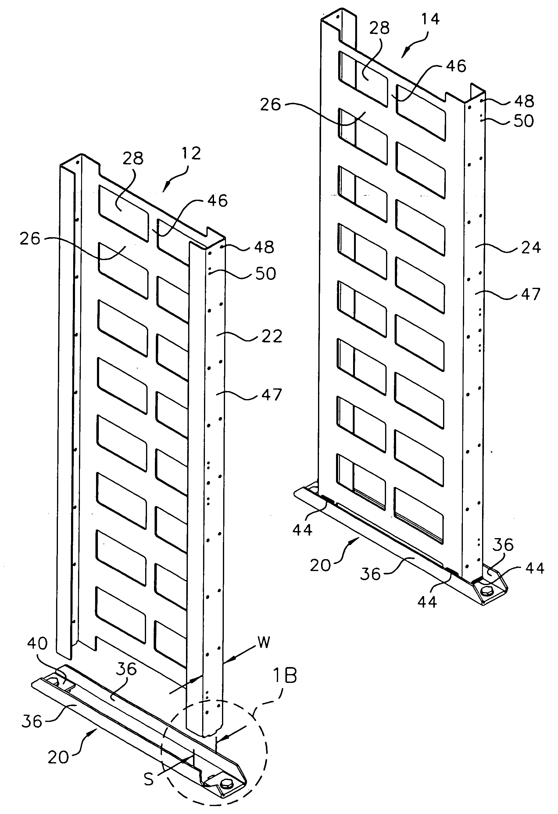
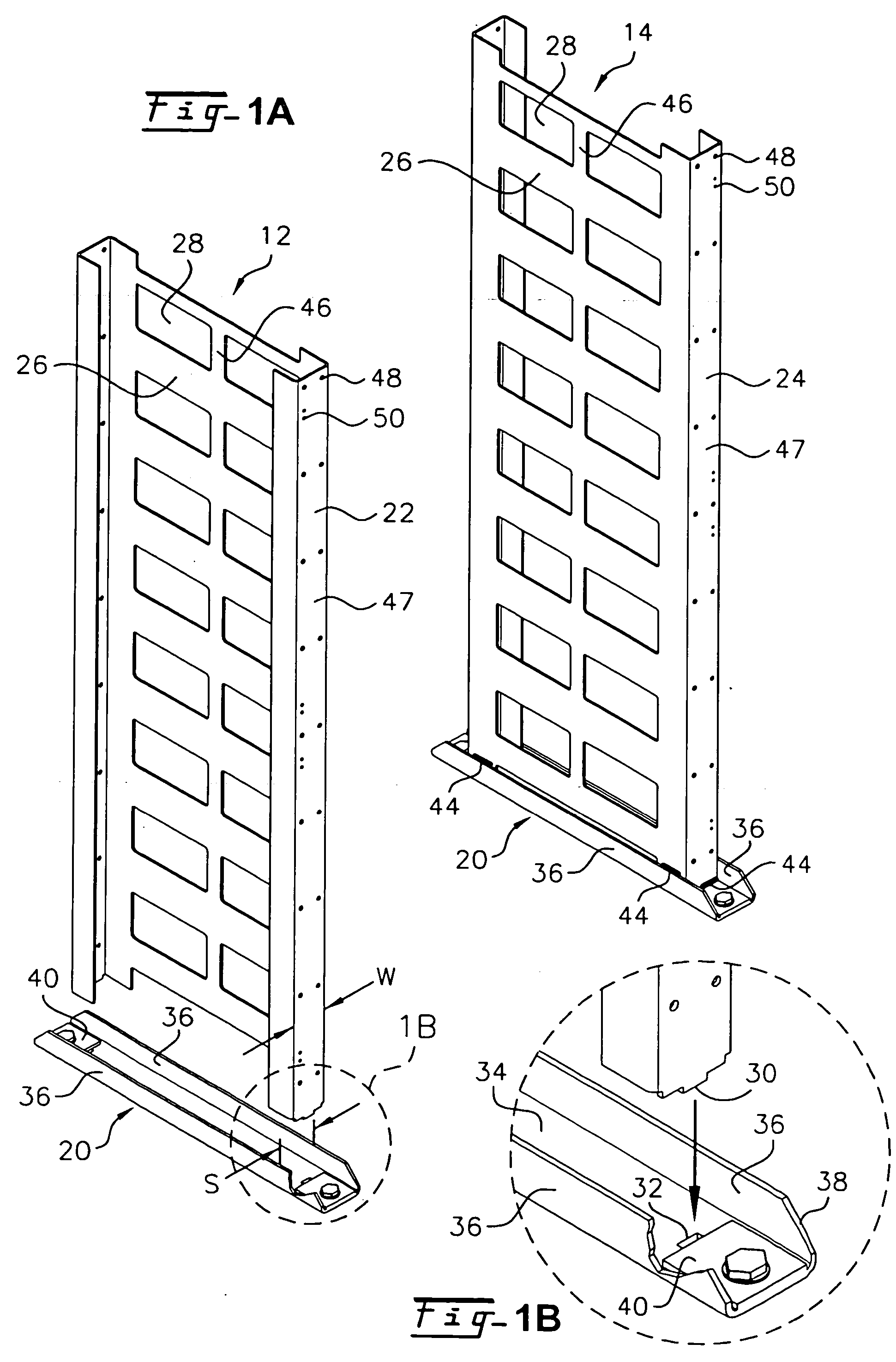
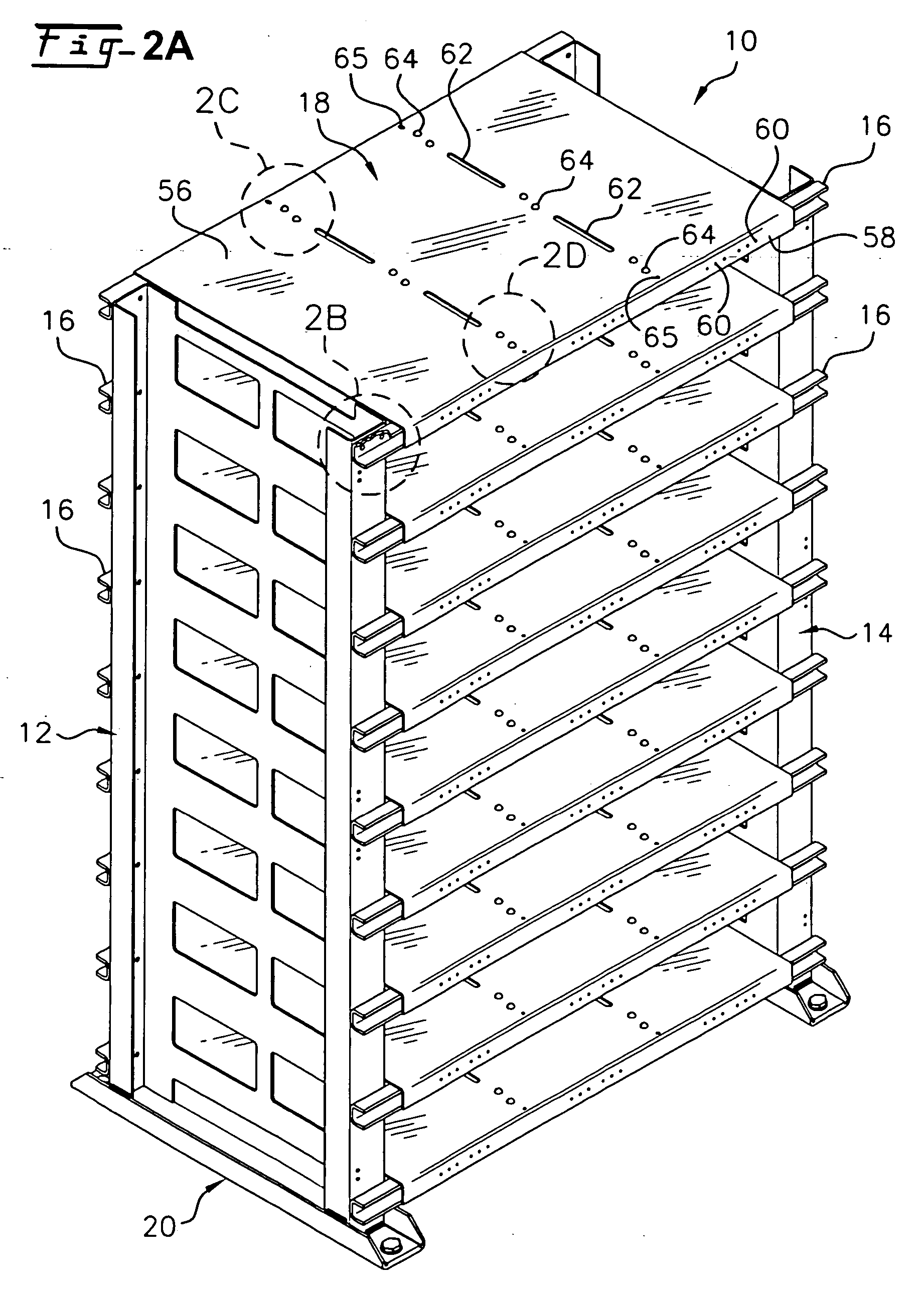
[0042] Referring now to the drawings and particularly to FIG. 2 thereof, there is shown a battery rack assembly and system including the unique features of the present invention which is generally designated by the numeral 10. The battery rack assembly 10 essentially comprises a pair of spaced apart end frames 12 and 14, a series of shelf support channels 16 which connect the end frames 12 and 14 and shelves 18 spanning the support channels which are spaced apart vertically to define a series of compartments for storing batteries in jackets in a manner described in more detail hereafter. The end frames 12 and 14 are rigidly supported in base channels 20) which can be anchored to a support surface such as a concrete floor in a commercial building.

[0043] Considering now the components of the battery rack assembly 10 in more detail and with specific reference to the end frames 12 and 14, each end frame may be fabricated from a single sheet of sheet metal punched and formed to the conf...


PUM

PropertyMeasurementUnit
seismic stressaaaaaaaaaa
widthaaaaaaaaaa
distanceaaaaaaaaaa

Abstract

A frame device for supporting objects such as batteries during seismic stress, comprising a pair of end frame members mounted in upstanding spaced apart relation by a plurality of vertically spaced elongated channel support members secured at opposite terminal ends to the vertical columns of the end frame members, shelves for supporting batteries spanning the channel support members and defining a plurality of compartments for the batteries, each end frame member being formed of a single sheet material shaped to define vertical columns and a web extending between the end columns, a pair of anchors, means for securing the end frames to the anchors, and means defining a plurality of openings in the web of each end frame generally aligned with the compartments formed by the shelves to provide horizontal ventilation of batteries mounted in the compartments.

Description

[0001] This is a continuation of Parent application Ser. No. 09 / 989,502 filed on Nov. 20, 2001 and entitled BATTERY RACK AND SYSTEM and claiming the benefit of Provisional Application, Ser. No. 60 / 294,144, filed on May 30, 2001.FIELD OF THE INVENTION [0002] The present invention relates to a rack for supporting and storing objects and more specifically to a battery rack system and apparatus having a plurality of compartments for supporting batteries and other heavy objects designed to survive seismic forces during earth tremors and the like. The invention relates specifically to frames forming part of what is known as an uninterruptable power source. BACKGROUND OF THE INVENTION [0003] There is a need, particularly in the telecommunications industries, for a back up power source to maintain operations when the primary power source shuts down. These systems generally comprises a plurality of valve regulated lead acid batteries (VRLA) generally of a two volt size which are typically co...

Claims


Application Information

Patent Timeline
Patent Type & Authority Applications(United States)
IPC IPC(8): A47F7/00H01M10/50H01M50/204H01M50/224H01M50/262H01M50/264H01M50/291H05K7/16
CPCH01M10/647H01M10/627H01M10/6566H01M10/613H01M10/6562Y02E60/10H01M50/204H01M50/224H01M50/264H01M50/291H01M50/262
Inventor MARRAFFA, ANDREW
Owner KIM MFG
Why Eureka
Try Eureka