Spread illuminating apparatus with light conductive plate having polygonal configuration

a technology of illuminating apparatus and polygonal configuration, which is applied in the direction of lighting and heating apparatus, planar/plate-like light guides, instruments, etc., can solve the problems of increasing the number of components, increasing the manufacturing cost, and consuming an increased electric power, and achieves the effect of efficient illumination and minimal power consumption

Inactive Publication Date: 2005-11-24
MINEBEA CO LTD
View PDF2 Cites 58 Cited by
  • Summary
  • Abstract
  • Description
  • Claims
  • Application Information

AI Technical Summary

Benefits of technology

[0016] Consequently, the direction of light emitted from a spot-like light source can be optimized by appropriately determining the angle of a side which has the spot-like light source disposed thereon, whereby the corner areas of a light conductive plate can be efficiently illuminated for achieving a uniform illumination across the light conductive plate with a minimum number of spot-like light sources and therefore at a minimum power consumption. And, a combination with a light scattering pattern formed on the light conductive plate generates synergistically a further uniform illumination.

Problems solved by technology

The LED is a spot-like light source and raises a problem with regard to achieving a uniform brightness across the light conductive plate.
The spread illuminating apparatuses described above, however, have following problems.
The problem shown in FIG. 6A can be solved by placing spot-like light sources respectively at all four corners, but this increases the number of components pushing up its manufacturing cost as well as consumes an increased electric power.
Consequently, the approach is still not satisfactorily successful, despite the provision of the mechanism13a for diffusing light horizontally, in efficiently illuminating the areas near the two adjacent corners, especially near the corner at a longer side thereby failing to provide a uniform illumination across the light conductive plate 11.

Method used


Image

  • Spread illuminating apparatus with light conductive plate having polygonal configuration
  • Spread illuminating apparatus with light conductive plate having polygonal configuration
  • Spread illuminating apparatus with light conductive plate having polygonal configuration

Examples


second embodiment

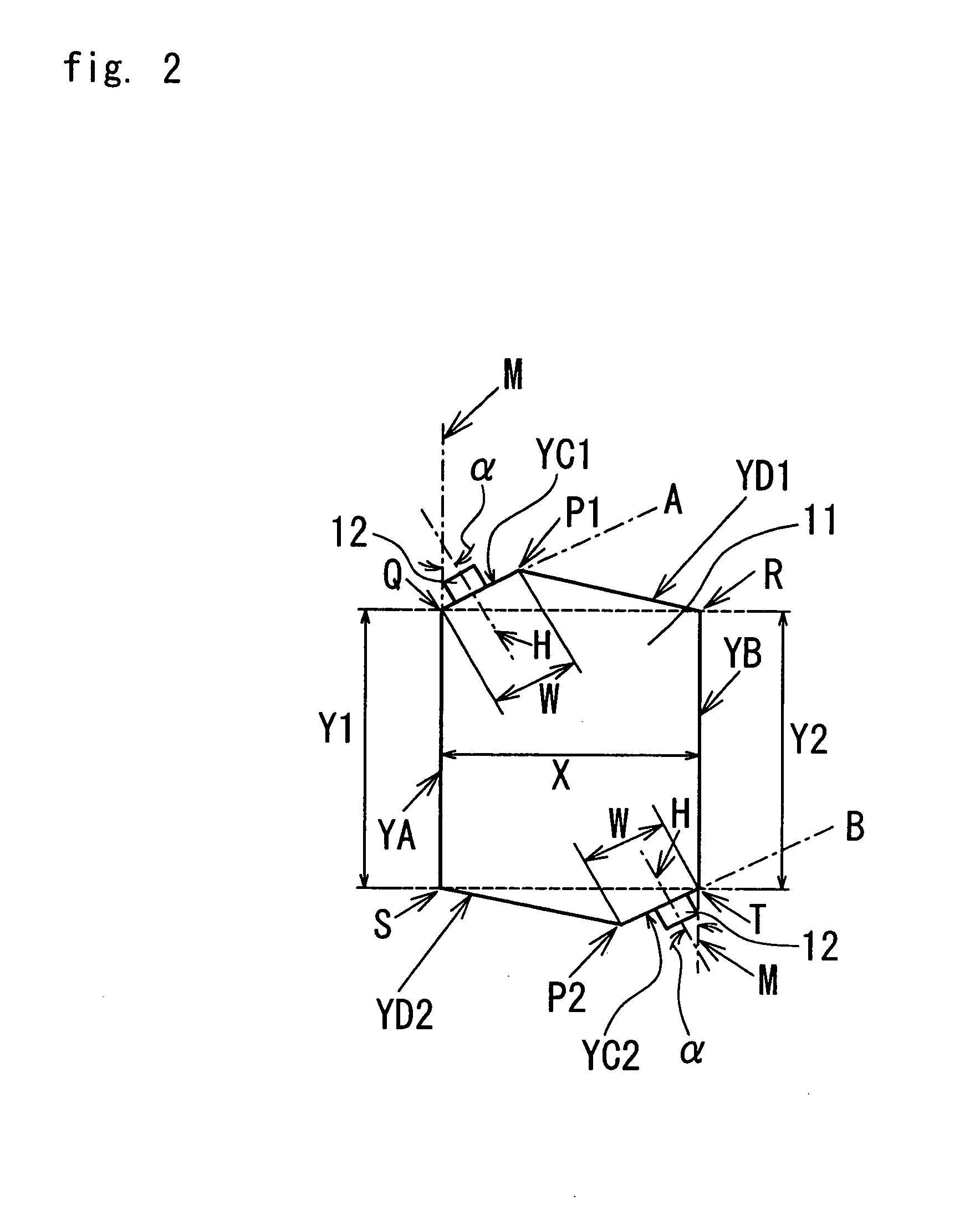
[0032] The aforementioned two triangles are shaped identical with each other, and positioned and oriented symmetric about the center point of the light conductive plate 11. The side surfaces YC1 and YC2 of respective triangles are parallel to each other and respectively have first and second LED's 12 as spot-like light source disposed thereon. Since the two LED's 12 are disposed so as to diagonally oppose each other, the spread illuminating apparatus is especially suitable when the ratio of the length Y to the distance X is larger than 2.5 and when a brighter illumination with an enhanced uniformity needs to be provided across the light conductive plate 11. An angle a formed between the side YA and a line H normal to the side YC is calculated by a formula: {55−(Y / X)×15} degrees.

[0033] The first and second LED's 12 disposed respectively at the side surfaces YC1 and YC2 are positioned so as not to protrude beyond respective lines M extended from the sides YA and YB, whereby the sprea...

third embodiment

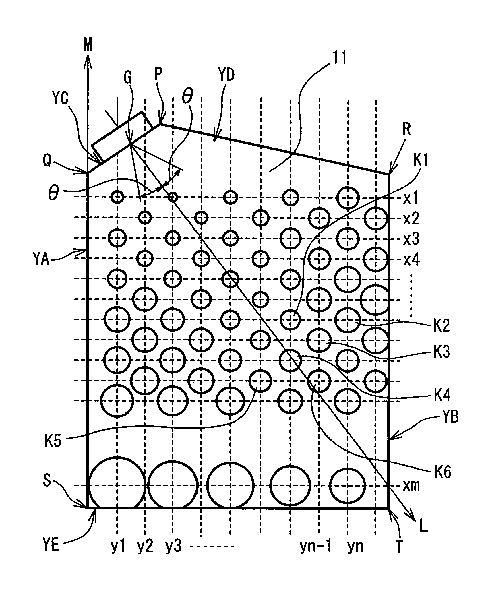
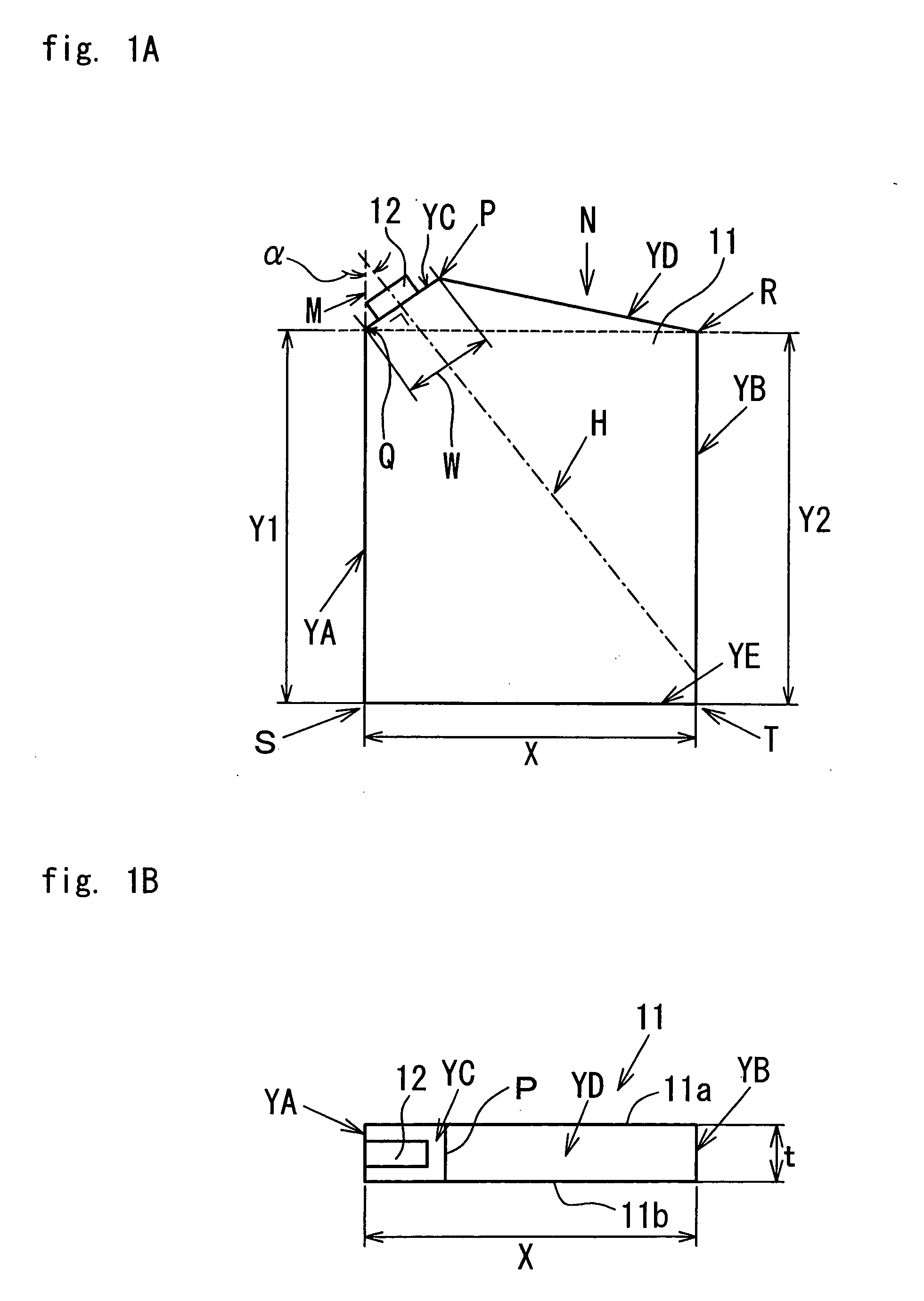
[0037]FIGS. 4A and 4B show spot by spot brightness across the light conductive plate 11 of the spread illuminating apparatus according to the In FIG. 4A, the lengths Y1 and Y2 of the sides YA and YB are equal (Y) to each other, the ratio of the length Y to the distance X is 4:3, and the angle α (refer FIG. 1A) is 35 degrees. As known from FIG. 4B, the ratio of the lowest brightness to the highest brightness is 0.88, which falls within practically acceptable limits.

[0038] In connection with the third embodiment, a light scattering pattern may be applied to the spread illuminating apparatus according to the second embodiment, which has two spot-like light sources disposed so as to oppose each other. In this case, the light scattering pattern consists of two sections patterned symmetric about the center point of the light conductive plate.


PUM

PropertyMeasurementUnit
inclination anglesaaaaaaaaaa
reflectanceaaaaaaaaaa
light conductiveaaaaaaaaaa

Abstract

In a spread illuminating apparatus comprising a spot-like light source, and a light conductive plate, the light conductive plate is shaped into a pentagon which has two sides thereof substantially parallel to each other, and which includes, as a part thereof, a triangle having its base defined by an imaginary line connecting respective straightly opposing ends of the two parallel sides, and the spot-like light source is disposed at a side of the pentagon constituting one of two hypotenuses of the triangle.

Description

BACKGROUND OF THE INVENTION [0001] 1. Field of the Invention [0002] The present invention relates to a spread illuminating apparatus for use with a liquid crystal display (LCD) device, and more specifically to a spread illuminating apparatus with a light conductive plate having a configuration suitable for spreading light from a spot-like light source in a uniform manner across a display screen. [0003] 2. Description of the Related Art [0004] A spread illuminating apparatus of side light type, which has a light source disposed so as to face one end surface of a light conductive plate, is heavily used as a subsidiary illuminating apparatus for an LCD device. In the side light type spread illuminating apparatus, the light source is shaped bar-like, for example a fluorescent lamp, and has a length substantially equal to the width of the light conductive plate, whereby the light conductive plate can be illuminated entirely in a uniform manner. In a device, such as a portable telephone, ...

Claims


Application Information

Patent Timeline
Patent Type & Authority Applications(United States)
IPC IPC(8): G02B6/00F21V8/00F21Y101/02G02F1/13357
CPCG02B6/0013G02B6/0061G02B6/0043
Inventor MIZUTANI, HITOSHIKAWASHIMA, SATOSHIKUNIMOCHI, TORUISHIGAMI, KATSUJI
Owner MINEBEA CO LTD
Why Eureka
Try Eureka