Disk array device

a technology of array devices and disks, applied in the direction of memory adressing/allocation/relocation, electrical apparatus casings/cabinets/drawers, instruments, etc., can solve the problems of data loss, data is retreated from the cache, and the response speed is slow, so as to improve the instantaneous power failure durability

Active Publication Date: 2005-11-24
RAKUTEN GRP INC
View PDF7 Cites 15 Cited by
  • Summary
  • Abstract
  • Description
  • Claims
  • Application Information

AI Technical Summary

Benefits of technology

The technical effect of this patent is to improve the ability of a battery or other backup power source to handle sudden power loss without shutting down the whole device. It also helps ensure optimal maintenance of the battery by avoiding overheating caused by multiple components within the device.

Problems solved by technology

This patent describes a problem with traditional disk arrays during power failures - they often use a single battery for back-up purposes which can lead to issues if there are multiple simultaneous power outages or other factors that affect the performance of the system.

Method used


Image

  • Disk array device
  • Disk array device
  • Disk array device

Examples


Embodiment Construction

[0036] Hereinafter, embodiments of the present invention will be detailed based on the drawings. Note that the same members are denoted by the same reference symbol in principle throughout all the drawings for explaining the embodiments and the repetitive descriptions thereof will be omitted.

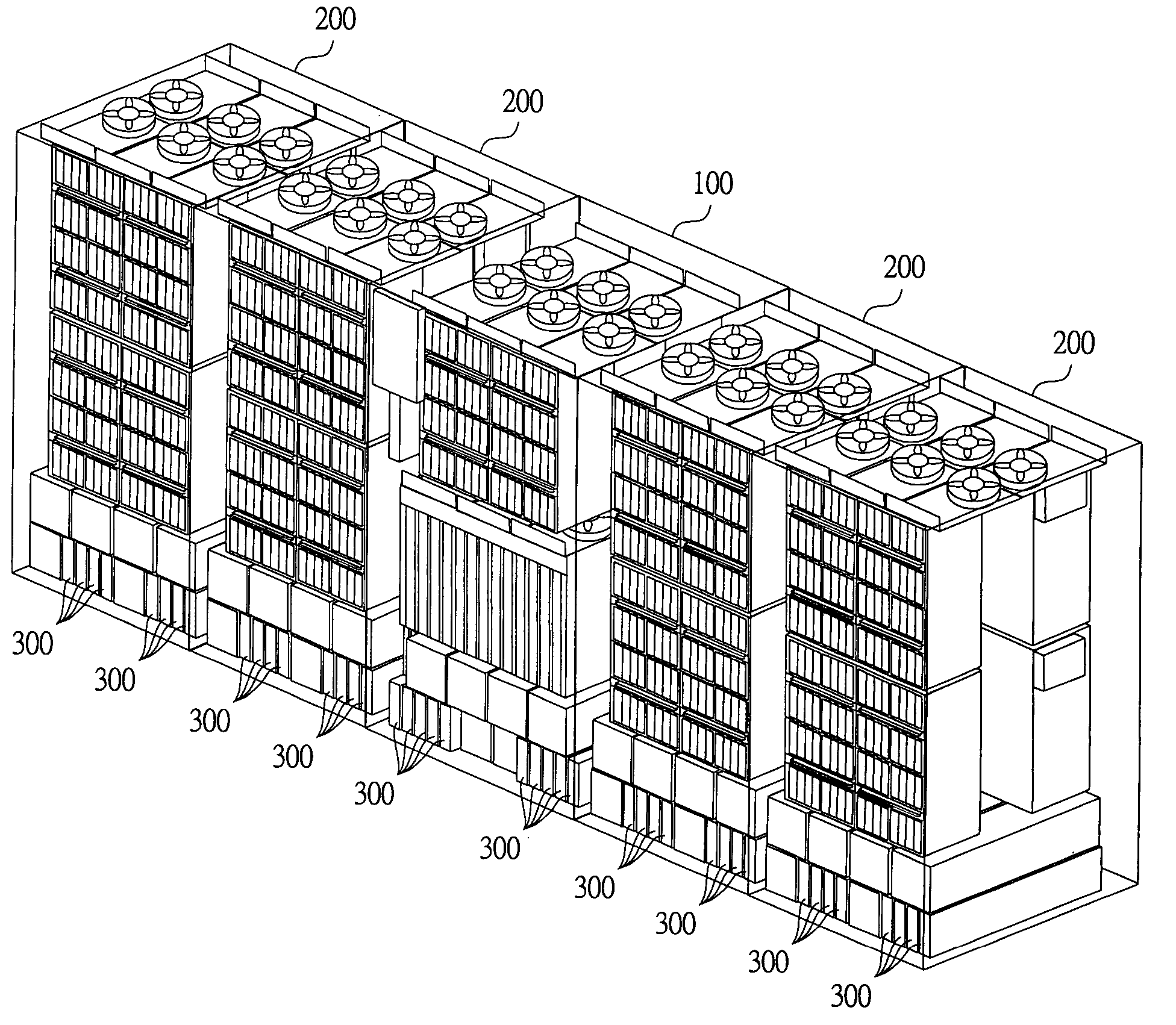
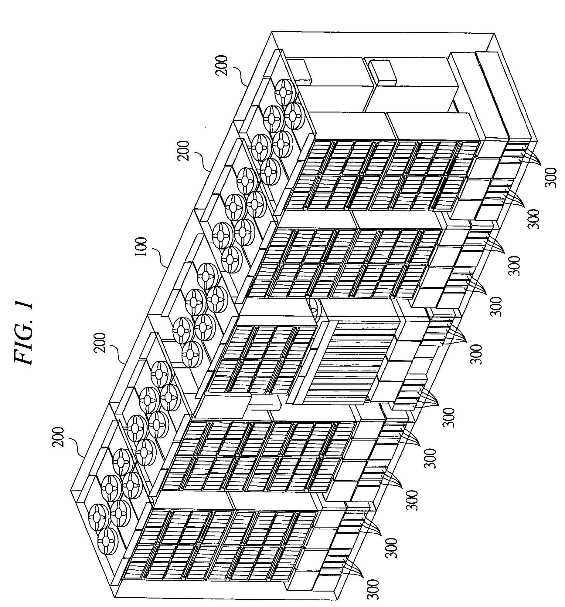
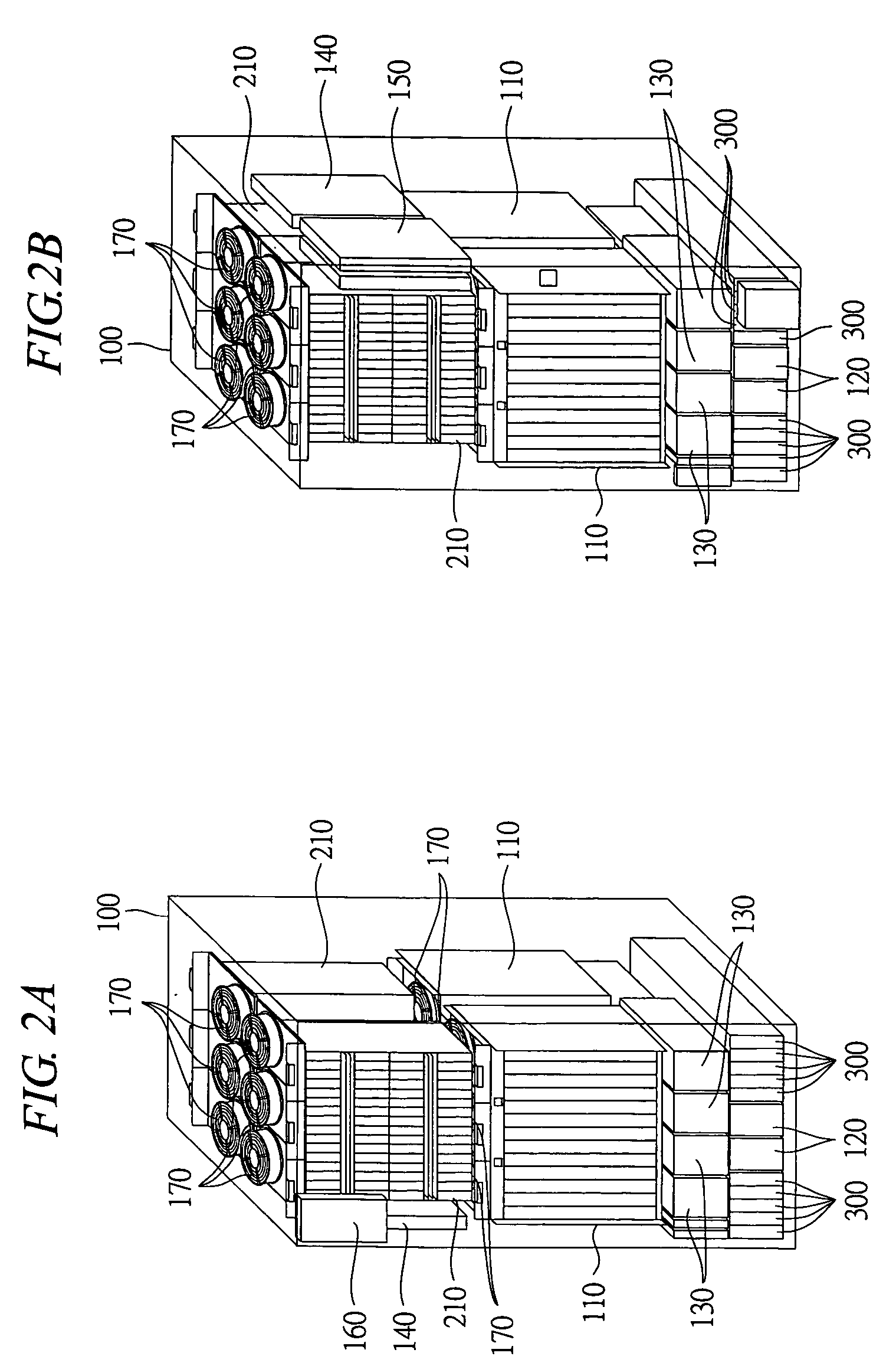
[0037] In reference to FIGS. 1 to 4, an example of an external structure of a disk array device according to an embodiment of the present invention will be described below. FIG. 1 is a diagram showing an example of an external structure of the disk array device according to the embodiment of the present invention. FIGS. 2A and 2B are diagrams showing an example of an external structure of a storage controlling unit, wherein FIG. 2A is a drawing viewed from a front direction and FIG. 2B is a drawing viewed from a rear direction. FIGS. 3A and 3B are diagrams showing an example of an external structure of a storage driving unit, wherein FIG. 3A is a drawing viewed from a front direction and FIG. 3...


PUM


Abstract

A disk array device can carry out battery backup including a destage process of data by a battery mounted in a case body of the disk array device and can enhance instantaneous power failure durability to an instantaneous power failure. A logic box mounts a channel controlling unit, a disk controlling unit, a cache memory and a switch; and a hard disk box mounts a plurality of memory devices. A battery box mounts a nickel hydrogen battery for supplying a backup power source at the time of a power failure and is disposed at a lower portion of each case body including the logic box and the hard disk box. The nickel hydrogen battery of the battery box is cooled through natural convection of air created inside the case body by a fan for cooling each of the logic box and the hard disk box.

Description


Claims


Application Information

Patent Timeline
Owner RAKUTEN GRP INC
Why Eureka
Try Eureka