Piezoelectric element and injector using the same

Inactive Publication Date: 2002-10-24
DENSO CORP
View PDF2 Cites 15 Cited by
  • Summary
  • Abstract
  • Description
  • Claims
  • Application Information

AI Technical Summary

Problems solved by technology

The internal electrode layers each have an end portion thereof exposed to the side surface of the laminate, and there is the possibility of shorting between the internal electrode layers.
Although an organic material has an insulating effect in a normal air atmosphere, it is not effective in the case where the piezoelectric element is used in a highly humid atmosphere, or in a liquid such as kerosene or gasoline.
Kerosene or gasoline contains water and therefore provides the same problem as a highly humid atmosphere.
Further, in the case where the interval between the internal electrode layers is extremely short (say, not more than 100 .mu.m), a shorting, though not a migration, may occur under a high voltage.
The capsule structure, however, increases the volume of the actuator as a whole and makes it difficult to reduce the size on the one hand and is accompanied with an increased number of parts resulting in an increased cost or a displacement loss.
Further, the gap between the capsule and the piezoelectric element deteriorates the heat radiation characteristic.
As far as an organic material is used, however, moisture is transmitted in some way or another, thereby unavoidably leading to shorting.
In the case where the organic insulating material develops cracking, however, a shorting occurs between the metal film and the internal electrode layers of the laminate.
Since the inorganic material is hard, however, the displacement due the operation of the laminate cannot be absorbed and a cracks develop.
In this method, however, moisture is transmitted by way of the slit in the same manner as through cracking.
Nevertheless, the organic insulat

Method used


Image

  • Piezoelectric element and injector using the same
  • Piezoelectric element and injector using the same
  • Piezoelectric element and injector using the same

Examples


first embodiment

[0107] As shown in FIG. 5, the piezoelectric element 9 comprises an organic insulating layer 41 formed over the entire side surface of the ceramic laminate 10 without any outer layer. In other words, the piezoelectric element 9 has a similar structure to the first embodiment except for the absence of the inorganic insulating layer 42.

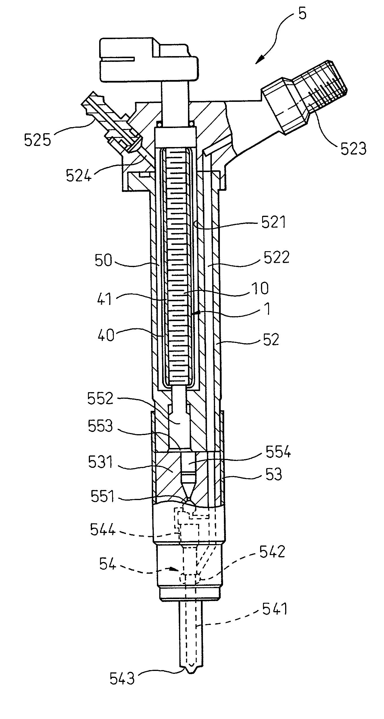
[0108] The piezoelectric element 9 (first comparison example), inserted into a bellows-type cover 95 as a capsule structure as shown in FIG. 6, is built in the injector 5 according to the second embodiment. This piezoelectric element 9 is compared with the piezoelectric element 1 according to the second (first) embodiment.

[0109] The item of comparison includes the heat value.

[0110] Under the same operating conditions, the piezoelectric element 9 (first comparison example) increases by 35.degree. C. in temperature, while the temperature increase of the piezoelectric element 1 (first embodiment) is not more than 5.degree. C.

[0111] This indicates that the ...

third embodiment

[0112] (Third Embodiment)

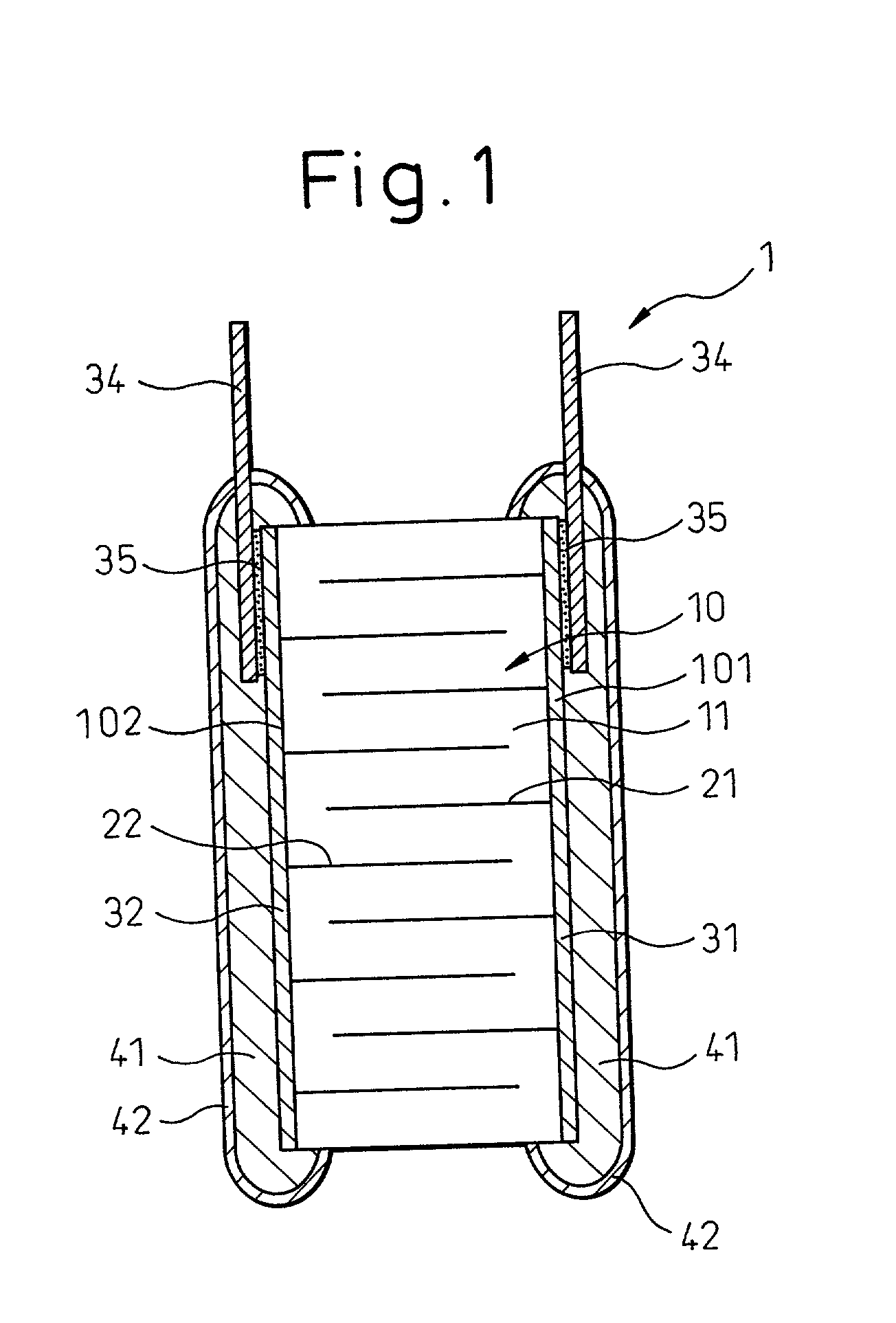
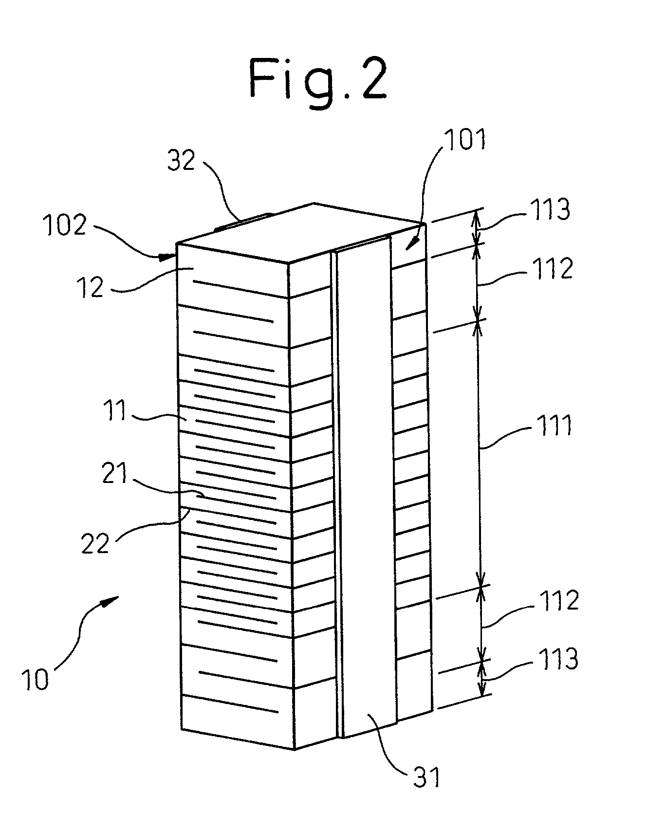
[0113] The piezoelectric element 1 according to this embodiment, as shown in FIG. 7, represents a case in which all the surfaces including the end surfaces along the direction of stacking as well as the side surface of the ceramic laminate 10 are covered with the organic insulating layer 41 and the inorganic insulating layer 42. The other points are similar to those of the first embodiment.

[0114] In this case, moisture intrusion can be prevented more securely. The other operation and effects are similiar to those of the first embodiment.

fourth embodiment

[0115] (Fourth Embodiment)

[0116] The piezoelectric element 1 according to this embodiment, as shown in FIG. 8, represents a case in which the organic insulating layer 41 and the inorganic insulating layer 42 are formed only on the side surface of the laminate, while no insulating layer is formed on the end surfaces along the direction of stacking the laminate. The other points are similar to those of the first embodiment.

[0117] In this case, the end surfaces along the stacking direction of the piezoelectric element 1 can be kept flat, and therefore a larger area can be secured for transmitting the displacement force. The other points of operation and effects are similar to those of the first embodiment.


PUM


Abstract

A piezoelectric element and an injector using the same piezoelectric element are disclosed, which are so high in reliability as not to be shorted even in a high humidity environment, are small in size, are low in cost and are high in heat radiation capability. The piezoelectric element comprises a ceramic laminate (10) including a plurality of ceramic layers of a piezoelectric ceramic (11) and a plurality of internal electrode layers (21, 22), stacked alternately. At least an organic insulating layer (41) of an organic material is formed on at least a part of the surface of the ceramic laminate (10), and at least an inorganic insulating layer (42) of an inorganic material is formed on the organic insulating layer (41).

Description

[0001] 1. Field of the Invention[0002] The present invention relates to a piezoelectric element used for a piezoelectric actuator and an injector using the piezoelectric element.[0003] 2. Description of the Related Art[0004] In recent years, the piezoelectric element used as a piezoelectric actuator has begun to employ a laminated structure generally comprising 100 to 700 piezoelectric ceramic layers as thin as 20 to 200 .mu.m and a plurality of internal electrode layers composed of a metal, which are stacked alternately in order to produce a large displacement with a low voltage.[0005] The internal electrode layers each have an end portion thereof exposed to the side surface of the laminate, and there is the possibility of shorting between the internal electrode layers. Various countermeasures have been taken.[0006] As an example, an organic material is arranged on the side surface of the laminate as an insulating structure. Although an organic material has an insulating effect in ...

Claims


Application Information

Patent Timeline
IPC IPC(8): F02M47/02F02M51/06F02M59/46H01L41/04H01L41/083H01L41/09
CPCF02M47/027F02M63/0026H01L41/0833H01L41/083H01L41/0533H10N30/883H10N30/503H10N30/50
Inventor SATO, KAZUHIDETERA, RYONOSUKEKAWAZOE, NAOYUKI
Owner DENSO CORP
Why Eureka
Try Eureka