Video editing apparatus and video editing method

a video editing and video processing technology, applied in the field of video editing apparatus and video editing method, can solve the problems of std buffer overflow, inability to perform splicing operation, and inability to carry out splicing operation, so as to ensure the effect of data connection/splicing processing and not cause discontinuity in output data

Inactive Publication Date: 2005-11-24
SONY CORP
View PDF12 Cites 43 Cited by
  • Summary
  • Abstract
  • Description
  • Claims
  • Application Information

AI Technical Summary

Benefits of technology

[0019] It is a further object of the invention to provide an improved video editing apparatus and method that can readily perform a splicing operation of coded digital video data that has been packetized for transmission.
[0020] Another object of the invention is to provide an improved video processing apparatus and method that can readily perform a splicing operation of coded digital video data that has been packetized for transmission that avoids a discontinuity in the output data in the vicinity of the splicing operation.
[0021] A still further object of the invention is to provide an improved video processing apparatus and method that can readily perform a splicing operation of digital video data that has been packetized for transmission that avoids underflow or overflow of a VBV buffer provided in a system target decoder (STD) buffer.
[0024] In accordance with the invention, respective encoded video data streams within the received video data transport stream are disassembled into their respective original elementary data streams, and are stored in the predetermined storage. The amount of coding bits that will be generated upon receipt for data streams to be spliced to the plurality of elementary data streams is analyzed, and based on the result of this analysis, the streams are spliced together, and a required amount of stuffing data is inserted at a link point to produce a continuous combined video data stream. The combined video data stream is output in accordance with an output timing determined on the basis of the amount of coding bits that will be generated upon receipt of the combined video data stream at a receiver. Thus, in accordance with the invention, it is possible to readily carry out data connection / splicing processing even with digital video data which is packetized for transmission, without causing a buffer in a receiver to underflow or overflow, and without causing a discontinuity in the output data.

Problems solved by technology

Thus, because the changing points of images are not at equal intervals as is the case of conventional frames, difficulties in performing the splicing operation are caused.
Thus, simply switching the data input from the first video data to the second video data may possibly cause the STD buffer to overflow.
Thus, the use of TS-packetized video data results in a problem that a splicing operation cannot be performed simply by switching video data from a first video data stream to a second video data stream.

Method used


Image

  • Video editing apparatus and video editing method
  • Video editing apparatus and video editing method
  • Video editing apparatus and video editing method

Examples


Embodiment Construction

(1) General Configuration of a Splicing Apparatus Constructed in Accordance with the Invention.

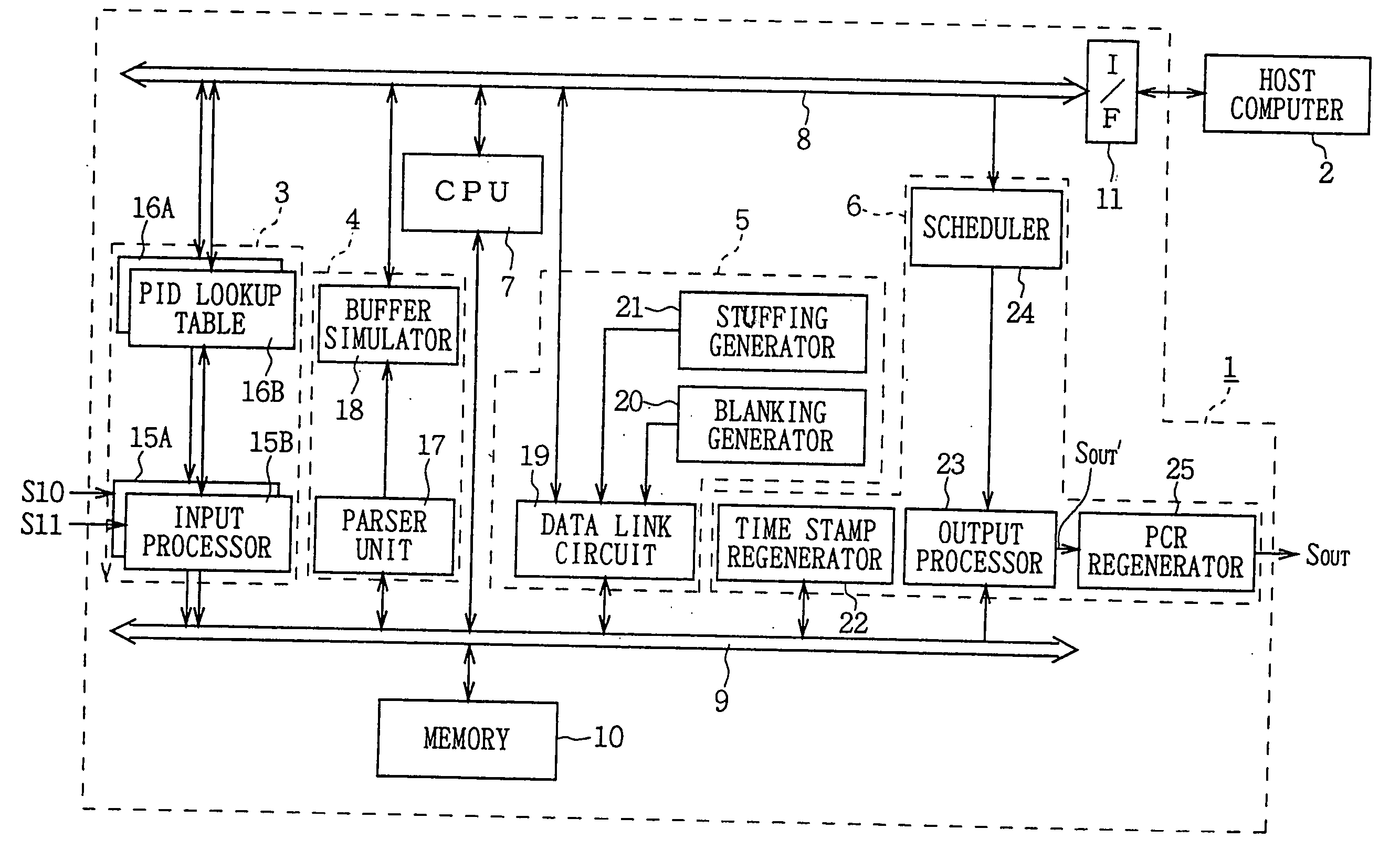
[0047] Referring first to FIG. 6, a splicing apparatus 1 is shown. In accordance with the invention, control information is supplied from an external host computer 2, and in accordance therewith, splicing apparatus 1 splices together pre-selected programs from multi-program transport streams S10, S11. Splicing apparatus 1 preferably resides in a main broadcasting station or in a local broadcasting station within a digital broadcasting system and operates to splice together video data of two different programs which have each been previously transformed into transport streams for transmission.

[0048] Making further reference to FIG. 6, the principle of a splicing operation performed in splicing apparatus 1 in accordance with the invention will be explained. Assume first that the transport stream S10 is multiplexed with digital video data of three programs A, C, E, while the transport stre...


PUM

PropertyMeasurementUnit
DAaaaaaaaaaa
DAaaaaaaaaaa
video data DAaaaaaaaaaa

Abstract

A video splicing apparatus for receiving a transport stream including a plurality of packetized encoded video data streams, and for splicing the encoded video data streams to generate a spliced video data stream. The video splicing apparatus includes an input processor for disassembling each of the plurality of packetized encoded video data streams in the transport stream into a pseudo-elementary stream before packetization, and for storing the disassembled pseudo-elementary streams in predetermined storage. An analyzer is also provided for analyzing the amount of coded bits of two data streams of the pseudo-elementary streams stored in the storage that will be generated upon decoding upon receipt of the two data streams to be subjected to a splicing operation. A data processor is provided for reading the data streams to be subjected to the splicing operation from the storage, splicing the streams, and inserting a desired amount of additional data at a splice point based on the result of the analysis by said analysis to produce a spliced video data stream and storing the spliced video data stream in the storage. An output processor is provided for determining output timing for the spliced video data stream based on the determined amount of coded bits, and outputting the spliced video data stream read from the storage based on the output timing.

Description

BACKGROUND OF THE INVENTION [0001] The present invention relates generally to a video editing apparatus and a video editing method and more particularly to a video editing apparatus and a video editing method that are particularly suitable for application in a splicing apparatus used for switching and connecting transport stream (TS) packetized video data. [0002] A variety of compression encoding schemes have been proposed as techniques for reducing the amount of information necessary to encode and represent video images and audio information associated therewith. A representative one of such compression encoding schemes is called Moving Picture Experts Group Phase 2 (MPEG2) that has been standardized by institutes such as the International Organization for Standardization (ISO) and so on. The MPEG2 compression encoding scheme has been standardized for purposes of transmitting video and audio data, and includes separate standards for video and audio data, respectively. [0003] Digita...

Claims


Application Information

Patent Timeline
Patent Type & Authority Applications(United States)
IPC IPC(8): H04N5/92G11B20/10H04N5/00H04N5/91H04N7/24H04N7/52H04N19/00H04N19/13H04N19/146H04N19/423H04N19/46H04N19/48H04N19/50H04N19/503H04N19/593H04N19/70H04N21/234H04N21/236H04N21/24
CPCH04N21/23424H04N7/52H04N21/2401H04N21/236H04N21/23611H04N7/54H04N21/23608H04N21/858
Inventor KITAMURA, TAKUYA
Owner SONY CORP
Why Eureka
Try Eureka