Method and apparatus for incorporating lumens into the wall of a tubular extrusion

a tubular extrusion and wall technology, applied in the field of extrusion heads, can solve the problems of lumen formation, both cosmetically and functionally undesirable, and achieve the effect of reducing the number of lumens

Inactive Publication Date: 2005-11-24
CANGEN HLDG
View PDF12 Cites 24 Cited by
  • Summary
  • Abstract
  • Description
  • Claims
  • Application Information

AI Technical Summary

Benefits of technology

[0019] Briefly described, a polymer extrusion head in accordance with the invention for extruding continuous shapes having one or more lumens or stripes therein includes an inner extrusion mandrel and an outer extrusion body and die. An annular flow path for polymer is formed therebetween, similar to the pri

Problems solved by technology

At least two significant problems are known in forming lumens in the prior art.
Second, because the lumen pipes extend from the mandrel, they must necessarily intersect the conical portion thereof

Method used


Image

  • Method and apparatus for incorporating lumens into the wall of a tubular extrusion
  • Method and apparatus for incorporating lumens into the wall of a tubular extrusion
  • Method and apparatus for incorporating lumens into the wall of a tubular extrusion

Examples


Embodiment Construction

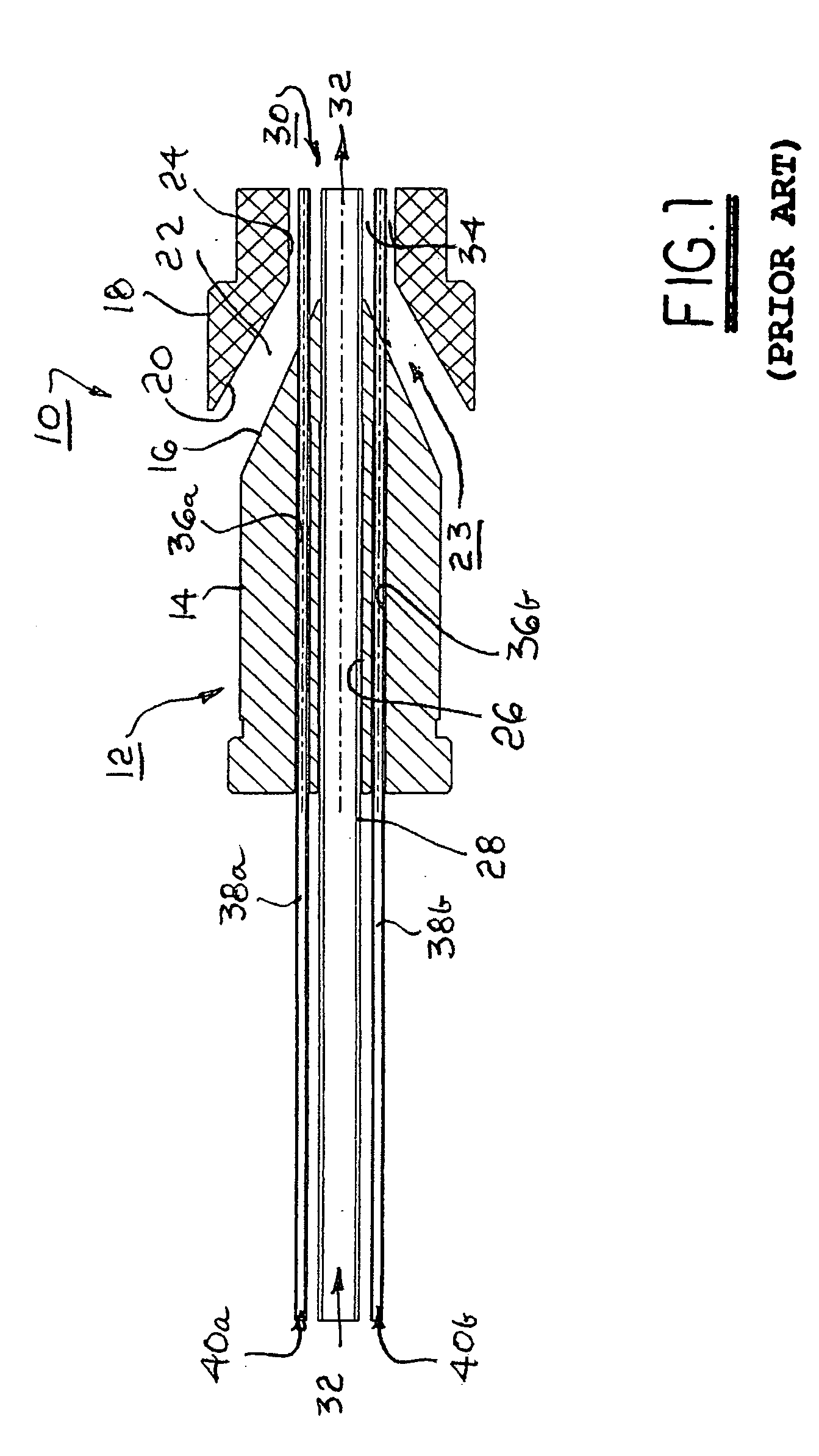
[0031] Referring to FIG. 1, there is shown a portion of a typical prior art apparatus 10 for extruding a tubing extrudate having a central opening and two diametrically opposed lumens. Apparatus 10 includes a mandrel 12 having a cylindrical portion 14 (for forming a cylindrical flow passage with an outer cylindrical body, not shown) and a tapered portion 16. An extrusion die 18 includes a conically tapered entrance 20, for forming with portion 16 a conically tapered flow chamber 22 for extrudate material 23, typically a molten polymer, and a non-tapered passage 24, which may be cylindrical or any other cross-sectional shape required in the extrusion. An axial central bore 26 in mandrel 12 supports a pipe 28 extending to the end 30 of die 18 for providing air 32 to support the central opening in the extrusion. Pipe 28 also functions as an extrusion tip for forming a non-tapered flow chamber 34 terminating at die end 30.

[0032] Mandrel 12 is further provided with first and second bore...


PUM

PropertyMeasurementUnit
Luminous fluxaaaaaaaaaa
Angleaaaaaaaaaa
Angleaaaaaaaaaa

Abstract

A polymer extrusion head for forming continuous shapes having one or more lumens therein. The head includes an extrusion mandrel and die. At least one lumen pipe is disposed radially through a port in the die to intersect the polymer flow in the annular region between the tip and the die. The lumen pipe is a welded assembly having a 90° turn formed as a mitered joint with zero bend radius. The lumen pipe is held in a pin vise engaged in the die such that position of the lumen pipe may be readily adjusted. Axial and radial positions are established during assembly by means of a gauge block. A plurality of lumen pipes may be accommodated for a plurality of lumens by a manifold distribution system including individual lumen pipe assemblies.

Description

TECHNICAL FIELD [0001] The present invention relates to method and apparatus for extrusion forming of molten polymer material; more particularly, to extrusion heads for continuous extruding of hollow or solid shapes; and most particularly, to method and apparatus for forming longitudinal voids or inclusions in such extruded shapes. BACKGROUND OF THE INVENTION [0002] Extrusion heads for continuous extrusion forming of continuous plastic elements having specific cross-sectional shapes are well known. Such extruded elements may include, for example, pipes, rods, moldings, tubings, and the like. [0003] In a typical prior art extrusion system, solid pellets of the thermoplastic material to be used are fed into a progressive-screw extruder wherein the pellets are liquefied under high pressure and are injected into an extrusion head. Such injection may be made axially of the extrusion head, as is commonly done for extrusion of solid shapes and tubes, or transversely of the extrusion head, ...

Claims


Application Information

Patent Timeline
IPC IPC(8): B29C48/06B29C48/09B29C48/11B29C48/32B29C48/325B32B1/08
CPCB29C47/0023Y10T428/139B29C47/0028B29C47/003B29C47/12B29K2995/002B29K2995/0021B29L2023/007B29L2031/60B29L2031/601B29L2031/7542B29C47/021B29C47/062B29C47/065B29C47/0026B29C48/09B29C48/10B29C48/11B29C48/12B29C48/151B29C48/19B29C48/21B29C48/304B29C48/32B29C48/06
Inventor ANAND, PREMCHAPIN, JOSEPH T.
Owner CANGEN HLDG
Why Eureka
Try Eureka