Valved catheter

Active Publication Date: 2005-11-24
CR BARD INC
View PDF99 Cites 45 Cited by
  • Summary
  • Abstract
  • Description
  • Claims
  • Application Information

AI Technical Summary

Benefits of technology

[0010] Accordingly, a valved catheter is described herein that includes an integral valve system intended to remain patent for the life of the catheter, which may be several years. During the life of the catheter, the valve should maintain functionality to provide multiple functions, including, but not limited to, one or more of the following examples: (a) sealing off the open end of the catheter during placement into the patient's circulation system, (b) sealing the catheter tube except when being accessed by an accessing device, such as a syringe or guidewire, to prevent blood loss or air embolism, (c) providing unobstructed flo

Problems solved by technology

This gas can compromise the circulation of blood through the lungs, causing serious injury or death.
In addition, for medical procedures requiring the implantation of a dual lumen catheter (e.g., hemodialysis catheter, etc.), it would be very difficult to tunnel the bifurcation connected to the proximal end of the catheter.
The sealing valve does not completely prevent air or fluid leakage, but relies on a second user compressible valve to provide a complete seal.
In short, there

Method used


Image

  • Valved catheter
  • Valved catheter
  • Valved catheter

Examples


Embodiment Construction

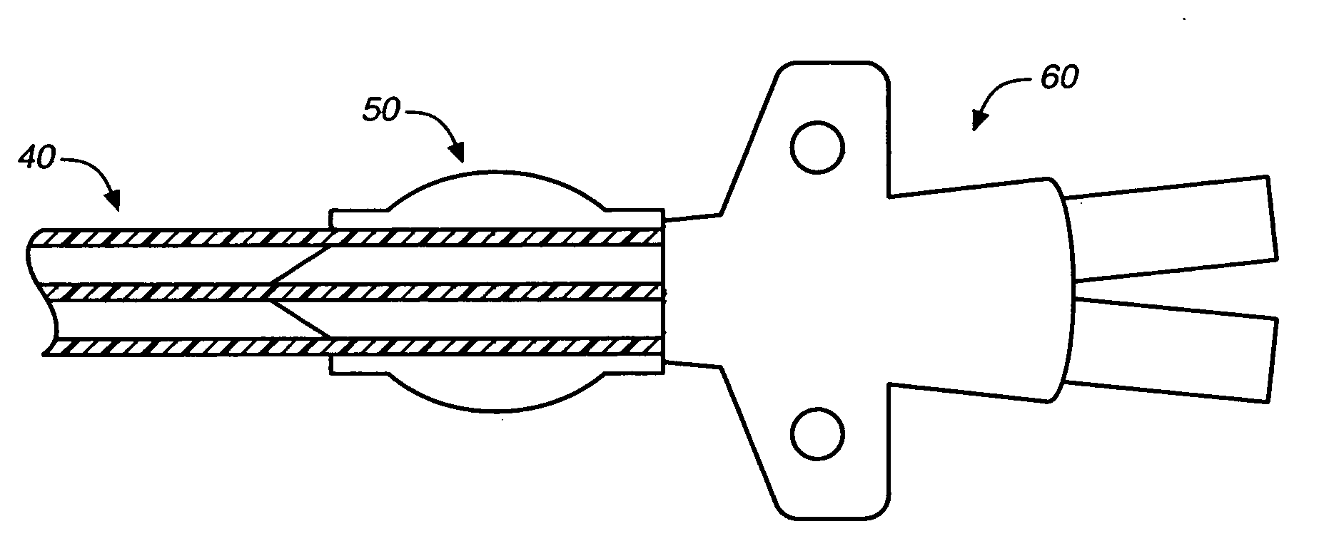
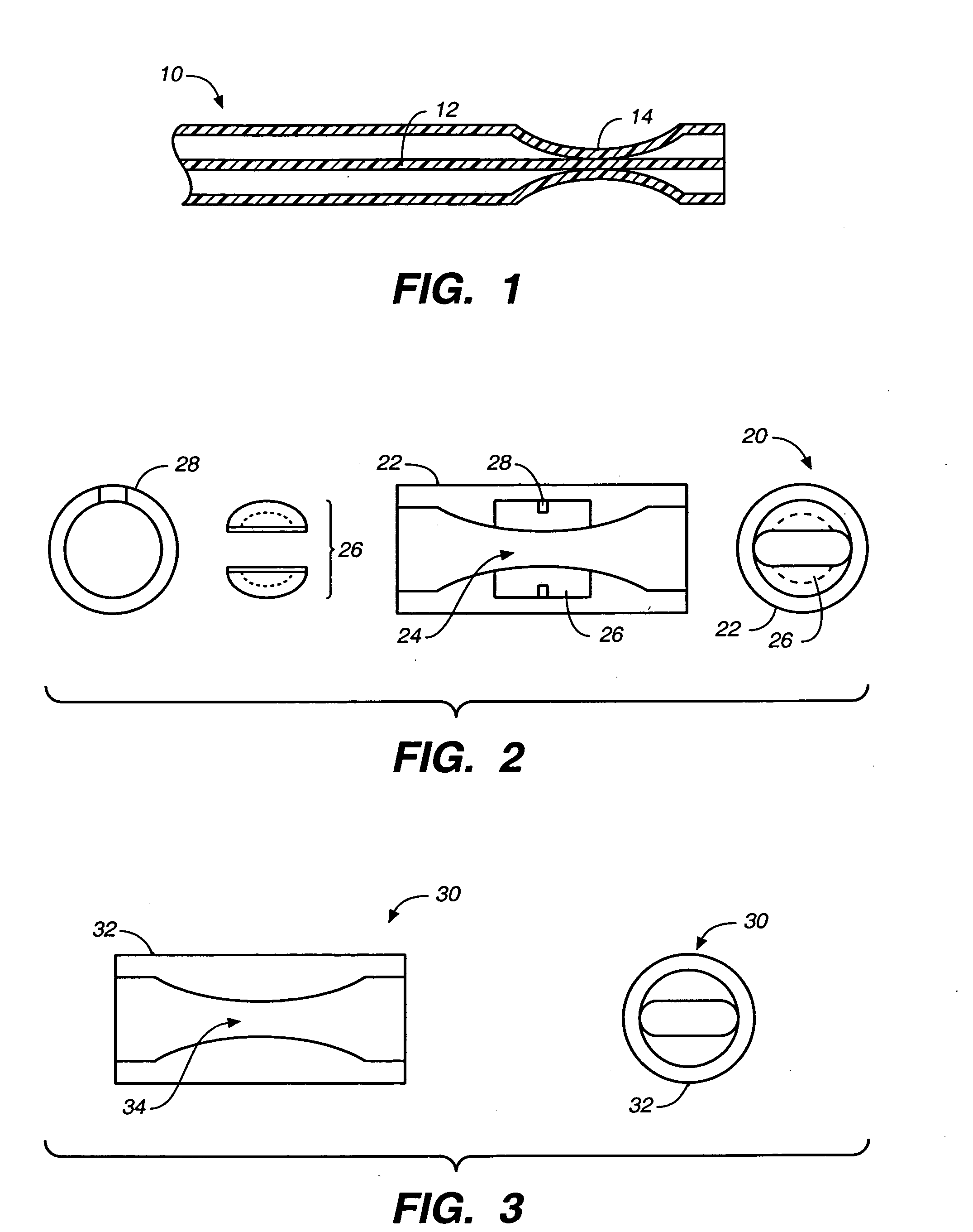
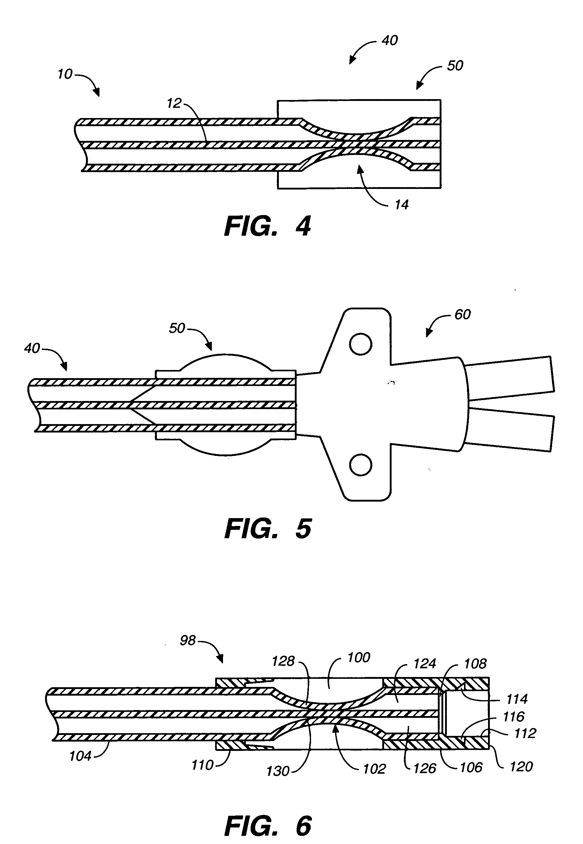
[0048] The following detailed description should be read with reference to the drawings, in which identical reference numbers refer to like elements throughout the different figures. The drawings, which are not necessarily to scale, depict selective embodiments and are not intended to limit the scope of the invention. The detailed description illustrates by way of example, not by way of limitation, the principles of the invention. This description will clearly enable one skilled in the art to make and use the invention, and describes several embodiments, adaptations, variations, alternatives and uses of the invention, including what is presently believed to be the best mode of carrying out the invention.

[0049] Before describing the present invention, it is to be understood that unless otherwise indicated this invention need not be limited to applications in humans. As one of ordinary skill in the art would appreciate, variations of the invention may be applied to other mammals as w...


PUM


Abstract

A valved catheter that allows placement and withdrawal of an accessing device or attachable unit without the risk of air embolism or blood loss. In one variation, the valved catheter includes a catheter tube having a necked portion in its proximal end that forms an integral valve, the necked portion being surrounded by a compression sleeve that biases the valve in a closed position. In another variation, the valved catheter is a dual lumen catheter with a corresponding bifurcating extension for engaging the valves in the catheter in order to establish fluid communication through the catheter.

Description

CROSS-REFERENCE TO RELATED APPLICATIONS [0001] This application is a continuation-in-part of U.S. patent application Ser. No. 10 / 803,207, entitled “VALVED CATHETER,” filed Mar. 18, 2004, and this application is also a continuation-in-part of U.S. patent application Ser. No. 11 / 076,564, entitled “MULTIFUNCTION ADAPTOR FOR AN OPEN-ENDED CATHETER,” filed Mar. 8, 2005, which is a continuation-in-part of U.S. patent application Ser. No. 10 / 803,512, entitled “MULTIFUNCTION ADAPTOR FOR AN OPEN-ENDED CATHETER,” filed Mar. 18, 2004, each of which is incorporated herein by reference in its entirety.STATEMENT REGARDING FEDERALLY SPONSORED RESEARCH OR DEVELOPMENT [0002] Not applicable. REFERENCE TO A COMPACT DISK APPENDIX [0003] Not applicable. BACKGROUND OF THE INVENTION [0004] There are a variety of conditions that require injection of fluids into, or withdrawing fluids from, parts of a body below the surface of the skin of the body. During the procedure, symptomatic gas embolism can occur wh...

Claims


Application Information

Patent Timeline
IPC IPC(8): A61M5/00A61M25/00A61M39/28
CPCA61M25/0075A61M39/286A61M25/0097
Inventor ROME, GUY T.BARRON, WILLIAM R.HAMATAKE, BRET
Owner CR BARD INC
Why Eureka
Try Eureka