Cryoablation system capable of preventing fluid leakage

A technology for fluid leakage and catheter ablation, which is applied in the direction of cooling surgical instruments, parts of surgical instruments, medical science, etc. It can solve problems such as clogging for 2-3 seconds or even longer, detection response lag, detection lag, etc., to achieve Fast and effective detection without delay, prevent blood loss, and prevent air embolism

Pending Publication Date: 2020-03-24
CRYOFOCUS MEDTECH (SHANGHAI) CO LTD
View PDF0 Cites 3 Cited by
  • Summary
  • Abstract
  • Description
  • Claims
  • Application Information

AI Technical Summary

Problems solved by technology

The detection of liquid leakage by this method has the defect of detection lag, and it is inevitable that liquid (usually the patient's blood) will enter the catheter, thereby affecting the health of the patient
On the other hand, this method cannot avoid the risk of air embolism caused by gas entering the blood when the air pressure at the damaged catheter is greater than or equal to the blood pressure at the location of the catheter in the human body
In addition, since the photoelectric sensor needs to set the transmitter and receiver in the catheter, it will inevitably increase the outer diameter of the catheter, and then there is a problem that it cannot adapt to some blood vessels
Third, the sensor needs power supply lines and signal lines, and at least four wires need to be installed in the catheter. Adding four wires in the narrow space of the catheter is likely to affect its performance
Therefore, th

Method used


Image

  • Cryoablation system capable of preventing fluid leakage
  • Cryoablation system capable of preventing fluid leakage
  • Cryoablation system capable of preventing fluid leakage

Examples


Embodiment 1

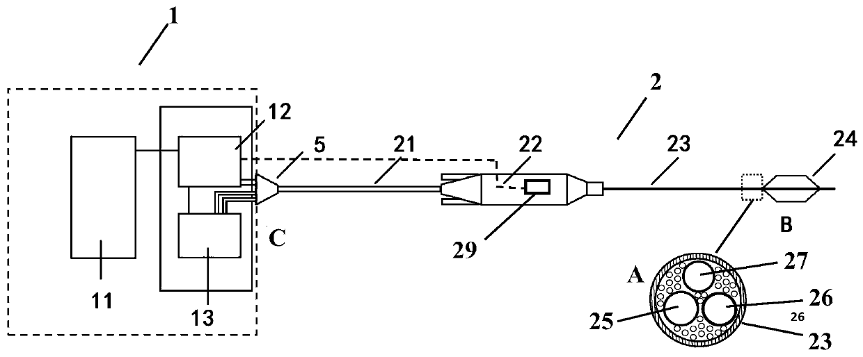
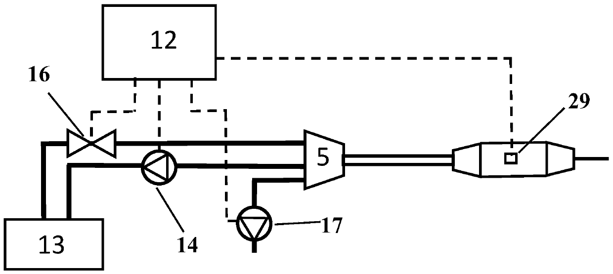
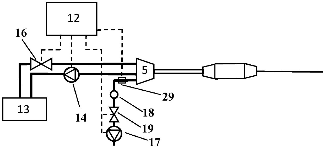
[0058] Such as Figure 1 to Figure 1 As shown in 0, a cryoablation system that can prevent fluid leakage is composed of a cryoablation device 1 and a cryoablation catheter 2. The cryoablation device includes a human-computer interaction module 11, a control module 12, and an air circuit module 13. The human-computer interaction module 11 is electrically connected to the control module 12, and the control module 12 is electrically connected to the gas circuit module 13. The cryoablation catheter 2 includes a catheter elongated shaft 23, and the catheter elongated shaft 23 The catheter handle 22 arranged at the proximal end, the freezing unit 24 arranged at the far end of the catheter elongated shaft 23, the air inlet tube 25 and the return air tube 26 arranged in the catheter elongated shaft 23, the air inlet tube 25 The air return pipe 26 is in fluid communication with the inner cavity of the freezing unit 24, and a water vapor sensor 29 is arranged in the cryoablation system,...

Embodiment 2

[0086] The difference between this embodiment and the first embodiment is that a guide wire lumen 27, a thermocouple 3 and a safety device 4 are arranged in the cryoablation catheter 2. Such as figure 1 and Figure 4 As shown, a cryoablation system that can prevent fluid leakage is composed of a cryoablation device 1 and a cryoablation catheter 2. The cryoablation device includes a human-computer interaction module 11, a control module 12, and an air circuit module 13. The computer interaction module 11 is electrically connected to the control module 12, and the control module 12 is electrically connected to the gas circuit module 13. The cryoablation catheter 2 includes a catheter slender shaft 23, and the catheter slender shaft 23 The catheter handle 22 arranged at the proximal end, the freezing unit 24 arranged at the distal end of the elongated catheter shaft 23, the air inlet tube 25, the air return tube 26 and the guide wire lumen 27 arranged in the elongated catheter s...

Embodiment 3

[0095] The difference between this embodiment and the second embodiment lies in that the structure of the safety device 4 is different. Such as Figure 13 and Figure 14 As shown, the safety device 4 is the openings 43 and 44 respectively arranged on the distal parts of the positive lead 31 and the negative lead 32, and the openings 43 and 44 are arranged in the liquid blocking mechanism 28 The openings 43 and 44 expose the conductive metal wires in the positive lead 31 and the negative lead 32, and the exposed conductive metal wires in the positive lead 31 and the negative lead 32 are not directly touch.

[0096] In one embodiment, the cryoablation device is provided with a catheter connection end 5, one end of the catheter connection end 5 is fixedly connected to the gas circuit module 13, and the other end of the catheter connection end 5 is connected through a flexible connection. The tube 21 is connected to the catheter handle 22, the air inlet pipe 25, the air return ...


PUM


Abstract

The invention relates to a cryoablation system capable of preventing fluid leakage. The system is composed of cryoablation equipment and a cryoablation catheter. The cryoablation equipment comprises ahuman-computer interaction module, a control module and a gas path module. A human-computer interaction module is electrically connected with the control module. The control module is electrically connected with the gas path module. The gas path module is connected with the cryoablation catheter. The cryoablation catheter includes a catheter slender shaft. A catheter handle is arranged at the proximal end of the catheter slender shaft, a freezing unit is arranged at the distal end of the catheter slender shaft, and an intake pipe and a return pipe are arranged in the cavity of the catheter slender shaft. The intake pipe and the return pipe are communicated with a fluid in the inner cavity of the freezing unit. A water vapor sensor is arranged in the cryoablation system, is communicated with a fluid in the catheter slender shaft, and is electrically connected with the control module. The system can effectively detect and prevent the safety risks of catheter liquid leakage and greatly reduce the risks in the application process of the cryoablation system.

Description

technical field [0001] The application belongs to the field of minimally invasive interventional therapy, and in particular relates to a cryoablation system capable of preventing fluid leakage. Background technique [0002] Cryoablation is a new technology in the treatment of cardiac arrhythmias. The principle is to take away the tissue heat through the heat absorption and evaporation of the liquid refrigerant, lower the temperature of the target ablation site, and destroy the abnormal cells and tissues, so as to achieve the purpose of treatment. The catheters used in cryoablation need to go inside the human body and go deep into the lesion. The interventional catheter of any cryoablation system generally has the risk of being damaged, causing blood to enter the catheter and causing partial blood loss to the patient. In addition, if the air pressure at the damaged catheter is greater than or equal to the blood pressure at the location of the catheter in the human body, the ...

Claims


Application Information

Patent Timeline
IPC IPC(8): A61B18/02
CPCA61B18/02A61B2018/0022A61B2018/00577A61B2018/00821A61B2018/0212
Inventor 刁月鹏赵奎文陈熙
Owner CRYOFOCUS MEDTECH (SHANGHAI) CO LTD
Why Eureka
Try Eureka