Apparatus and method for automated test setup

a technology of automatic test setup and automatic testing, applied in the direction of marginal checking, error detection/correction, instruments, etc., can solve the problems of increasing the amount of setup time, consuming the process, and requiring several hours to set up a logic analyzer for probing signals from asics or fpgas

Inactive Publication Date: 2005-11-24
AGILENT TECH INC
View PDF4 Cites 31 Cited by
  • Summary
  • Abstract
  • Description
  • Claims
  • Application Information

AI Technical Summary

Problems solved by technology

Setting up a logic analyzer for probing signals from ASICs or FPGAs typically takes several hours.
Secondly, the engineer must manually identify a probe pin associated with each output pin.
First the process is time consuming.
So, when the number of signals increases, the amount of time for the setup increases.
Second, t

Method used


Image

  • Apparatus and method for automated test setup
  • Apparatus and method for automated test setup
  • Apparatus and method for automated test setup

Examples


Embodiment Construction

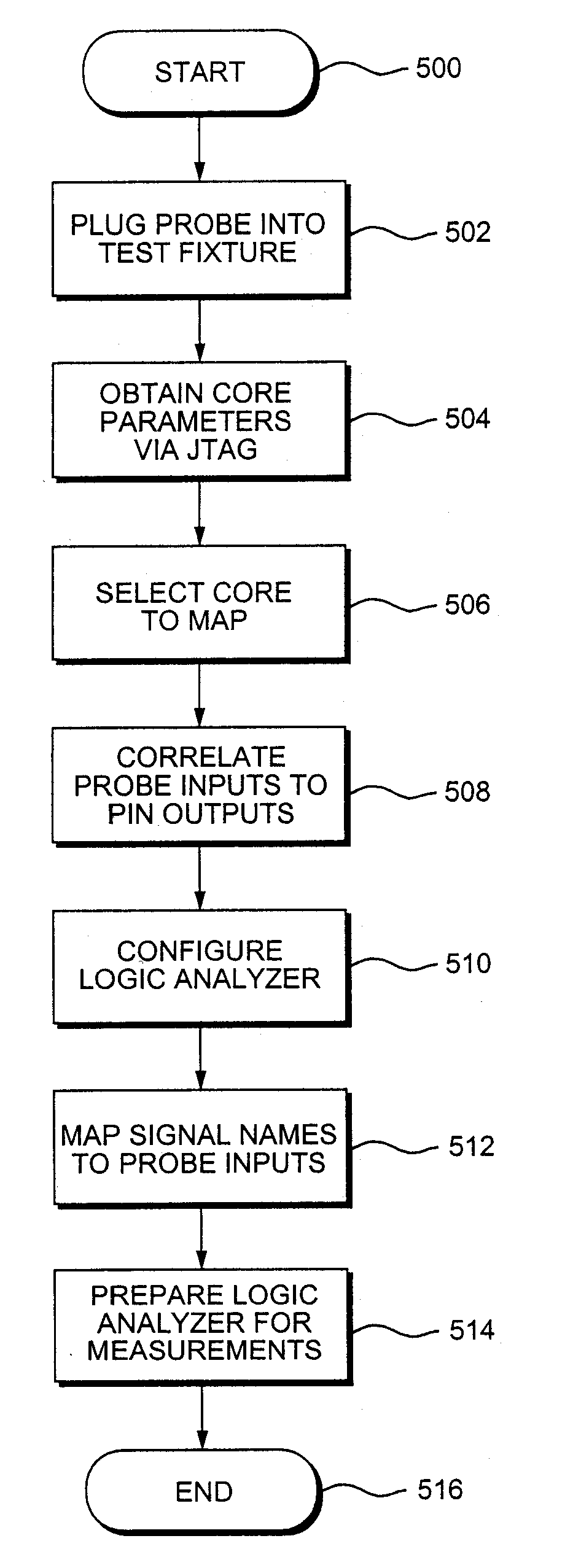
[0027] Reference will now be made in detail to the present invention, examples of which are illustrated in the accompanying drawings, wherein like reference numerals refer to like elements throughout. The detailed description which follows presents methods that may be embodied by routines and symbolic representations of operations of data bits within a computer readable medium, associated processors, logic analyzers, digital storage oscilloscopes, general purpose personal computers configured with data acquisition cards and the like. A method is here, and generally, conceived to be a sequence of steps or actions leading to a desired result, and as such, encompasses such terms of art as “routine,”“program,”“objects,”“functions,”“subroutines,” and “procedures.” These descriptions and representations are the means used by those skilled in the art effectively convey the substance of their work to others skilled in the art.

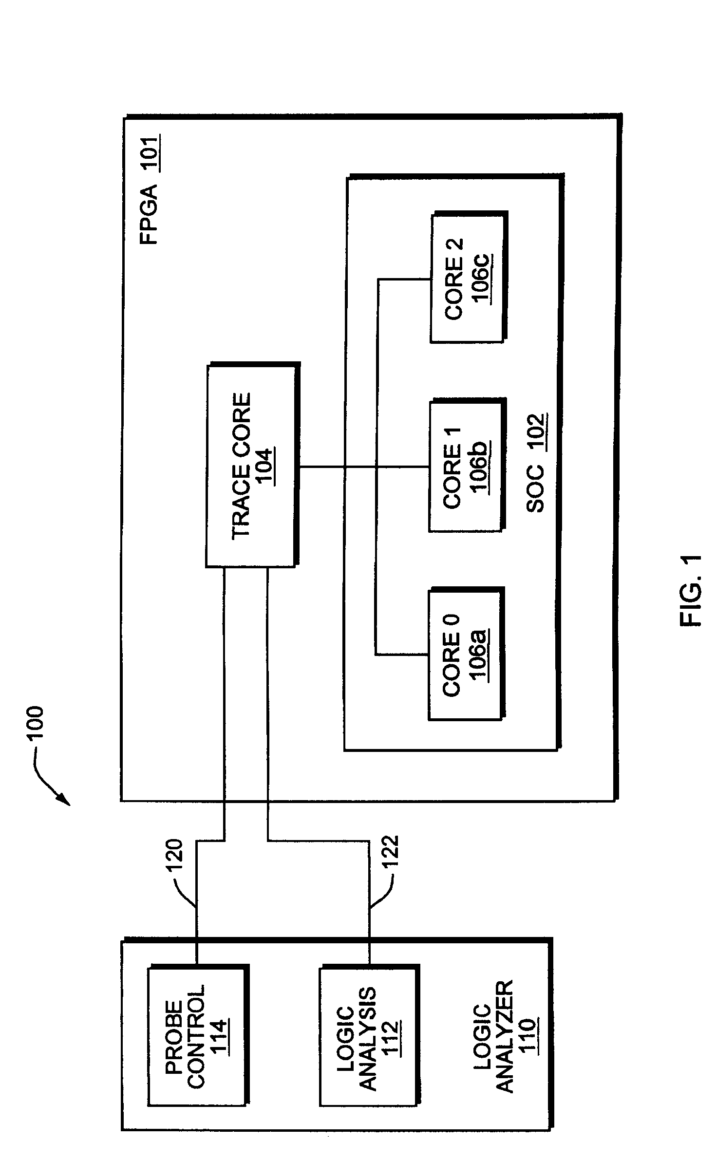
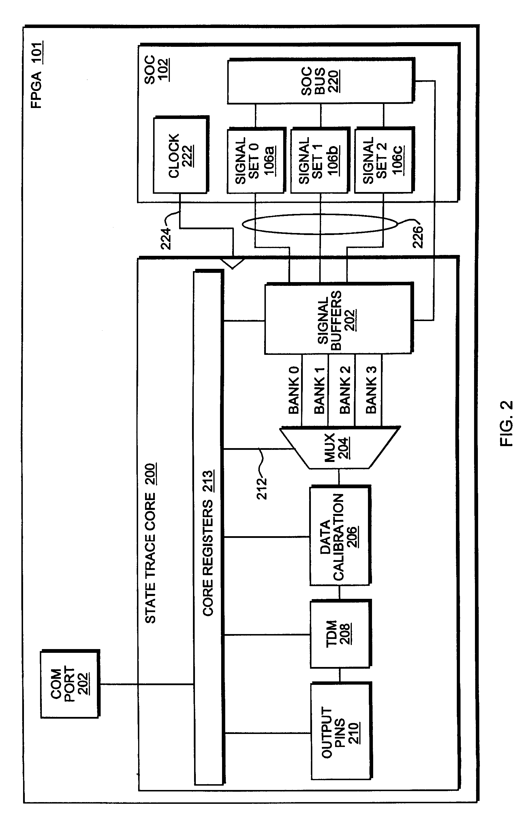
[0028] The apparatus and methods of the present invention will b...


PUM


Abstract

Apparatus and methods for setting up a test instrument to perform measurements on a circuit having a plurality of signal applied to a plurality of output pins. Configuration parameters including an identification of the output pins are retrieved and the test instrument is configured to interface with the output pins based on the configuration parameters. A list of output pins and a list of input lines associated with the test instrument are graphically displaying on a screen associated with the test instrument. Interacting with the graphical display, the user then associates each output pin with an input line to which each output pin is connected.

Description

CROSS REFERENCE TO RELATED APPLICATIONS [0001] The present application claims priority under 35 U.S.C. §120 to U.S. Provisional Patent Application Ser. No. 60 / 565,308, filed Apr. 26, 2004 entitled DYNAMIC IN-CIRCUIT PROBING OF FIELD PROGRAMMABLE GATE ARRAYS. The present application also claims priority under 35 U.S.C. §120 to U.S. patent application Ser. No. 10 / 923,460 filed Aug. 20, 2004 entitled APPARATUS AND METHOD FOR DYNAMIC IN-CIRCUIT PROBING OF FIELD PROGRAMMABLE GATE ARRAYS, which in turn claims priority to the '308 provisional patent application.BACKGROUND OF THE INVENTION [0002] Modern integrated systems, such as systems on a chip (SOCs); field programmable gate arrays (FPGAs) and application specific integrated circuits (ASICs) often contain features designed to facilitate in-circuit testing. The normal procedure, when doing in-circuit testing on large circuits such as field programmable gate arrays (FPGAs), is to feed the circuit real world stimuli throughout the operati...

Claims


Application Information

Patent Timeline
IPC IPC(8): G06F11/00G06F11/25
CPCG01R31/3177G01R31/3181G01R31/318519G06F11/25G01R31/3191G06F11/24G01R31/318533
Inventor WOODWARD, JOEL D.HERNANDEZ, ADRIAN M.SAMUELS, MASON B.STEWART, JAMES B. III.
Owner AGILENT TECH INC
Why Eureka
Try Eureka