Fuel rail pulse damper with improved end crimp

Inactive Publication Date: 2005-12-01
DELPHI TECH INC
View PDF7 Cites 5 Cited by
  • Summary
  • Abstract
  • Description
  • Claims
  • Application Information

AI Technical Summary

Benefits of technology

[0011] Briefly described, an internal pulse damper in accordance with the invention is formed from a length of tubular metal stock having a flat oval cross-section and ends flattened by crimping to form a captive-air pillow. The end crimps are improved through use of improved tooling to eliminate a creased are

Problems solved by technology

This results in stiffening of the end and changes the

Method used


Image

  • Fuel rail pulse damper with improved end crimp
  • Fuel rail pulse damper with improved end crimp
  • Fuel rail pulse damper with improved end crimp

Examples


Embodiment Construction

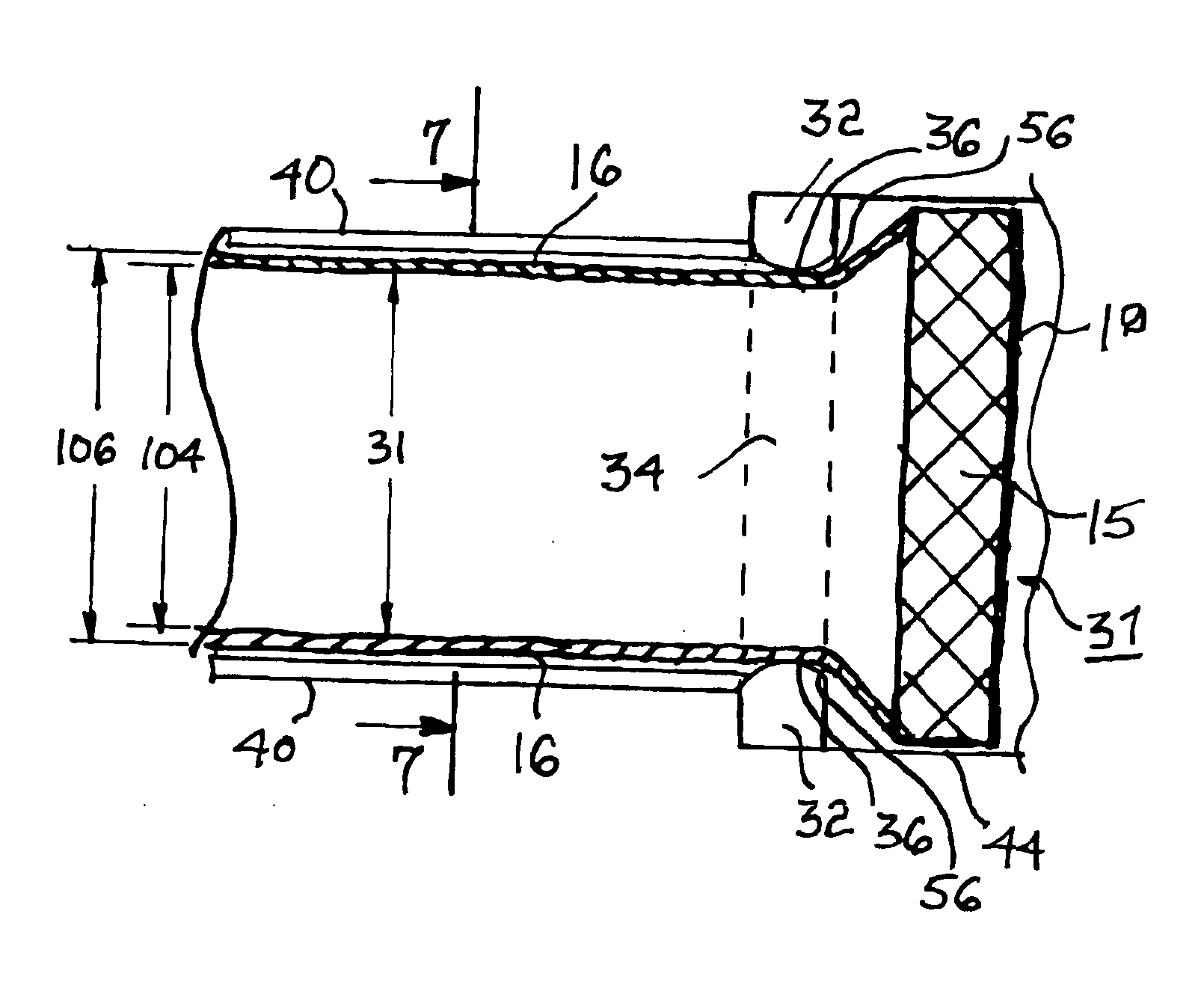
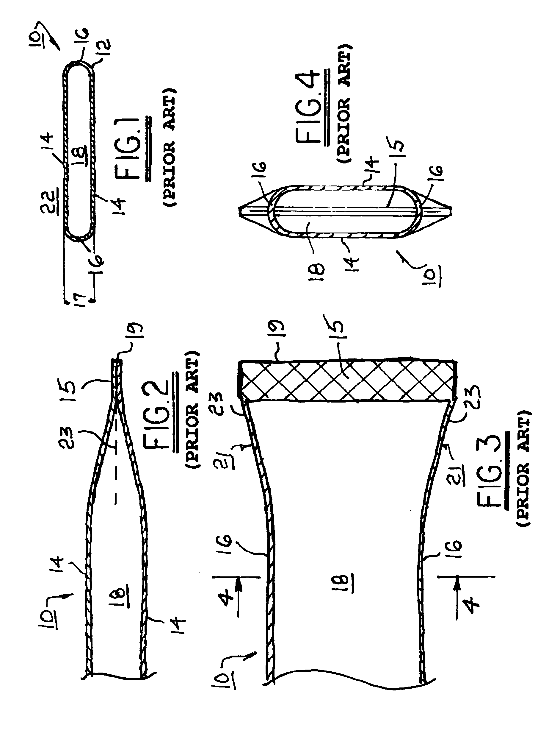
[0021] Referring to FIGS. 1 through 4, a prior art internal pulsation damper 10 for inclusion within a fuel rail for an internal combustion engine is formed as an elongate pillow 12, FIG. 1 showing a transverse cross-sectional view thereof. The shown cross-sectional shape is known in the art, and referred to herein, as a “flat oval.” Pillow 12 is provided with first and second diaphragm sides 14 separated and connected by longitudinal rigid short sides 16 of height 17 (typically about 3.41 mm) which are typically curved as shown such that the cross-sectional shape is a flat oval. Sides 14 are joined at the ends of pillow 12, as by compression of sides 14 (pinching) to form a crimp, defined by a flattened region 15 as shown in FIG. 2, and then welding 19 of sides 14 together as shown in FIGS. 2 and 3, to form a sealed chamber 18 within pillow 12. Chamber 18 is filled with a gas, preferably air. Pillow 12 is disposed within a fuel rail (not shown in FIGS. 1 through 4 but similarly to ...


PUM

PropertyMeasurementUnit
Lengthaaaaaaaaaa
Flexibilityaaaaaaaaaa
Widthaaaaaaaaaa

Abstract

An internal pulse damper for use in a fuel rail for an internal combustion engine. The damper is formed from a length of tubular metal stock having a flat oval cross-section and ends flattened by crimping to form a captive-air pillow. The end crimps are improved through use of tooling to eliminate a creased sidewall area vulnerable to stress failure in prior art pulse dampers. Such tooling includes constraints to prevent the tubing sides from flaring out and forming a longitudinal crease adjacent the end crimp during squeezing-shut of the tube end

Description

TECHNICAL FIELD [0001] The present invention relates to fuel rails for internal combustion engines; more particularly, to devices for damping pulses in fuel being supplied to an engine via a fuel rail; and most particularly, to an improved fuel rail internal damper having an improved end crimp for extending the useful life of the damper. BACKGROUND OF THE INVENTION [0002] Fuel rails for supplying fuel to fuel injectors of internal combustion engines are well known. A fuel rail is essentially an elongate fuel manifold connected at an inlet end to a fuel supply system and having one or more ports for mating with one or more fuel injectors to be supplied. [0003] Fuel rail systems may be recirculating, as is commonly employed in diesel engines. Fuel rail systems are more typically “returnless” or dead ended, wherein all fuel supplied to the fuel rail is dispensed by the fuel injectors. [0004] A well-known problem in fuel rail systems, and especially in returnless systems, is pressure pu...

Claims


Application Information

Patent Timeline
IPC IPC(8): F02M1/00F02M55/02F02M61/16F02M63/00
CPCF02M55/025Y10T29/49394F02M2200/315F02M61/168
Inventor BRAUN, CHARLES W.BECENE, AHMET T.CASS, CHRISTOPHER M.FURCHILL, PATRICK A.
Owner DELPHI TECH INC
Why Eureka
Try Eureka