Method and apparatus for measuring accumulated and instant rate of material loss or material gain

a technology of instant rate and material loss, applied in the direction of measuring devices, electric/magnetic thickness measurements, instruments, etc., can solve the problems of insufficient resolution of these techniques, inaccurate or misleading, and none of the techniques provide a fast measurement of instant rate of corrosion

Inactive Publication Date: 2005-12-01
METRICORR
View PDF8 Cites 7 Cited by
  • Summary
  • Abstract
  • Description
  • Claims
  • Application Information

AI Technical Summary

Benefits of technology

[0009] A particular advantage of the present invention is the provision of a temperature independent measurement of accumulated and instant rate of material loss or material gain accomplished without use of a temperature sensor device.
[0010] A further advantage of the present invention is the provision of measurement and balancing of real and imaginary voltage components variations endured by a measuring probe.
[0011] A particular feature of the present invention is the provision of compatibility of the present invention to numerous probes having different physical attributes and having different physical dimensions.
[0019] (g) a first sensor amplifier having a first sensor amplifier input connected to said first connector of said coated section of said metal element, having a second sensor amplifier input connected to said second connector of said non-coated section of said metal element, and having a first sensor output generating a first sensor amplifier output signal constituted by an amplification of said first metal element voltage, said second metal element voltage and / or a voltage difference between said second metal element voltage and said first metal element voltage,
[0020] According to the basic realisation of the first aspect of the present invention the voltage difference between the coated and non-coated section of the metal element or probe provides a measurement of accumulated corrosion, whereas the second resistance in conjunction with time related changes of the second resistance at one temperature provides a measurement of instant rate of material loss or material gain. The resistance of the metal element constituted by the first resistance and said second resistance of may be in a range from 4 μΩ to 4 KΩ such as ranges 4 mΩ to 400 mΩ or 10 mΩ to 100 mΩ.
[0021] The apparatus according to the first aspect of the invention provides the possibility to apply a wide variety of probes or metal elements for measuring accumulated or instant rate of material loss or material gain. This compatibility further ensures that the apparatus generates repeatable measurements irrespective of probe type.

Problems solved by technology

However, since these techniques require a conducting electrolyte system e.g. a stable water phase they are not applicable in a corrosion process when water is not continuously present.
Further, even though the requirements for performing electrochemical measurements are present inaccurate results may occur induced by additional current responses from redox-processes other than those involved in the particular corrosion process, which additional current responses may superimpose on the current response from the corrosion process and cause inaccurate or misleading results.
In addition, the interpretation of the results of a measurement performed using one of the generally applied electrochemical techniques often requires a specific expertise and knowledge of the user.
None of the techniques provides a fast measurement of instant rate of corrosion or in other words the resolution of these techniques is insufficient.
However, the resistance of the test coupon and the resistance of the reference coupon are highly temperature dependent.
Consequently, the effect of temperature variations from one measurement to another will cause unwanted inaccuracies in the measurements and decreases the comparability of the individual measurements included in a series of measurements.
However this kind of temperature compensation obviously introduces further inaccuracies in the measurement since the temperature characteristics of the temperature sensor device are not identical to the temperature characteristics of the test coupon or the reference coupon.

Method used


Image

  • Method and apparatus for measuring accumulated and instant rate of material loss or material gain
  • Method and apparatus for measuring accumulated and instant rate of material loss or material gain
  • Method and apparatus for measuring accumulated and instant rate of material loss or material gain

Examples


first embodiment

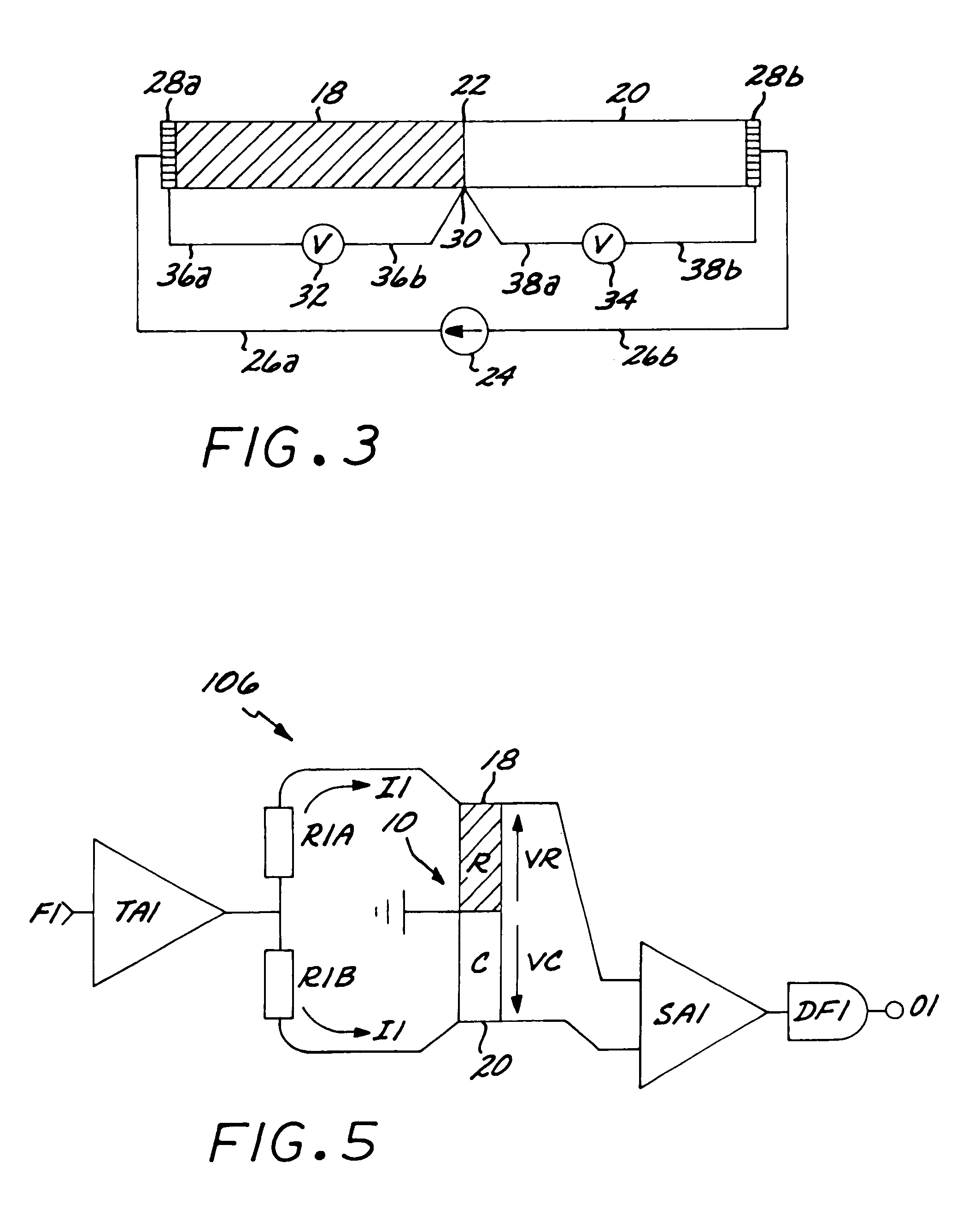
[0104] The implementation of the invention as described above will be described below with reference to FIGS. 5 to 9, including several alternative embodiments, which additionally may be implemented in numerous ways. The invention may be implemented in accordance with a first embodiment, comprising a bridge circuitry designated in its entirety by numeral 106 and shown as a circuit diagram in FIG. 5 having a power transmitter amplifier TA1 being supplied with an AC input signal at frequency F1.

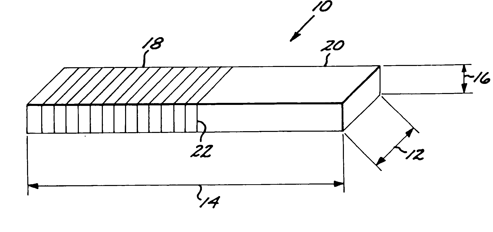
[0105] The power transmitter amplifier TA1 provides a current excitation output, which is split into two equal excitation currents I1 in to two lines. The first line is connected to the coated first section 18 of the metal element 10 via a resistor R1A. The second line is connected to the non-coated second section 20 of the metal element 10 via a resistor R1B. The resistors R1A and R1B provide similar electrical resistance, which resistance is substantially larger than the electrical resistance...

second embodiment

[0112] the invention in accordance with FIG. 6 further comprises a second power transmitter amplifier TA2 being supplied with a second alternating input signal at a second frequency F2.

[0113] The second power transmitter amplifier TA2 provides a second current excitation output having the second frequency F2, which current excitation output is split into two equal excitation currents I2 in to two lines. The second excitation current I2 is fed to the coated first section 18 and the non-coated second section 20 of the metal element 10 via resistors R2A and R2B, which resistors R2A and R2B are of the same order of magnitude as resistors R1A and R1B.

[0114] The first and the second input signals are fed to the first and second power transmitter amplifier TA1 and TA2 respectively through the input circuit 110 constituted by two the potentiometers P1 and P2. The potentiometers P1 and P2 provide two alternating voltage input signals to the first and second power transmitter amplifier TA1 a...

third embodiment

[0153]FIG. 9 shows a circuit diagram of a complete circuit 118 constituting the invention. The complete circuit 118 comprises all the features described with reference to FIGS. 1 through 8.

[0154] A first crystal designated by XO1 in FIG. 9 provides a first square-wave signal to a first four-quadrant phase splitter FS1. The first four-quadrant phase splitter FS1 provides square-wave signals in four phases at 0°, 90° 180° and 270° at a first frequency F1, i.e. shifted by a 90°-phase delay from each other.

[0155] Similarly a second crystal designated by XO2 provides a second square-wave signal to a second phase splitter FS2 providing four phase-signals at a second frequency F2, i.e., at 0°, 90°, 180° and 270° phases. These signals are used as phase reference inputs for five synchronous detectors DF1R, DF1I, DF2CR, DF2CI and DF2RR and as signal inputs for balance potentiometers I-BAL and R-BAL, power transmitter amplifiers TA1, TA2, TA3 and TA4 and first and second digital ladders LD1 a...


PUM

PropertyMeasurementUnit
resistancesaaaaaaaaaa
frequencyaaaaaaaaaa
voltagesaaaaaaaaaa

Abstract

Apparatus for measuring accumulated and instant rate of material loss or material gain of metal elements for the detection of metal deposition and corrosion includes a metal probe that is inserted into a measurement environment, causing the probe to experience metal deposition or corrosion. The probe has a corrosion-resistant first section and a corrodible second section. A temperature-compensated circuit receives an input signal from each of the first and second sections of the probe, whereby the circuit maintains a substantially constant voltage across the first section and generates a reference signal and a measurement signal. The circuit conditions and converts the reference signal and the measurement signal to produce first and second digitized output signals for inputting to a microprocessor.

Description

CROSS-REFERENCE TO RELATED APPLICATIONS [0001] This application is a Continuation-in-Part of co-pending application Ser. No. 10 / 166,571; filed Jun. 10, 2002, which, in turn, is a Continuation of International Application No. PCT / DK00 / 000689; filed Dec. 11, 2000. The disclosures of both of the aforementioned applications are incorporated herein by reference.FEDERALLY SPONSORED RESEARCH OR DEVELOPMENT [0002] Not Applicable BACKGROUND OF THE INVENTION [0003] This invention relates to a method and an apparatus for measuring accumulated and instant rate of material loss or material gain of metal elements for the detection of metal deposition (material gain) caused for example during deposition of coatings used in plating processes and corrosion (material loss) caused for example in pipelines during transportation of hazardous media. [0004] The state of the art provides several techniques for quantification of accumulated corrosion and instant corrosion rate as for example disclosed in Br...

Claims


Application Information

Patent Timeline
Patent Type & Authority Applications(United States)
IPC IPC(8): G01B7/06G01N17/00
CPCG01N17/00G01B7/06
Inventor NIELSEN, KAJ V.NIELSEN, LARS V.
Owner METRICORR
Why Eureka
Try Eureka