Method for performing an intake manifold injection

a technology of intake manifold and injection method, which is applied in the direction of electrical control, process and machine control, instruments, etc., can solve the problems of only partial conversion, severe damage to the catalytic converter or at least greatly shorten the lifetime, and the flow of fresh air is not easy to achieve. , to achieve the effect of preventing a heavy burden on the catalytic converter and increasing the torqu

Inactive Publication Date: 2011-02-24
ROBERT BOSCH GMBH
View PDF19 Cites 2 Cited by
  • Summary
  • Abstract
  • Description
  • Claims
  • Application Information

AI Technical Summary

Benefits of technology

[0014]By making use of the scavenging effect, the present invention should allow an increase in torque in a possible implementation for engines using intake manifold injection (SRE engines) and thus in engines using intake manifold injection or fuel injection i

Problems solved by technology

One disadvantage of the scavenging effect is that some of the fresh air flowing in through the intake valve goes directly to the exhaust gas system without having been involved in the combustion.
This has consequences for exhaust gas purification, e.g., using a three-way catalytic converter, so that the resulting conversion is only partial.
In the case of a stoichiometric conversion, there is also an exothermic reaction, which may severely damage the catalytic converter or at least greatly shorten its lifetime.
However, use of the systems known fr

Method used


Image

  • Method for performing an intake manifold injection
  • Method for performing an intake manifold injection
  • Method for performing an intake manifold injection

Examples


Embodiment Construction

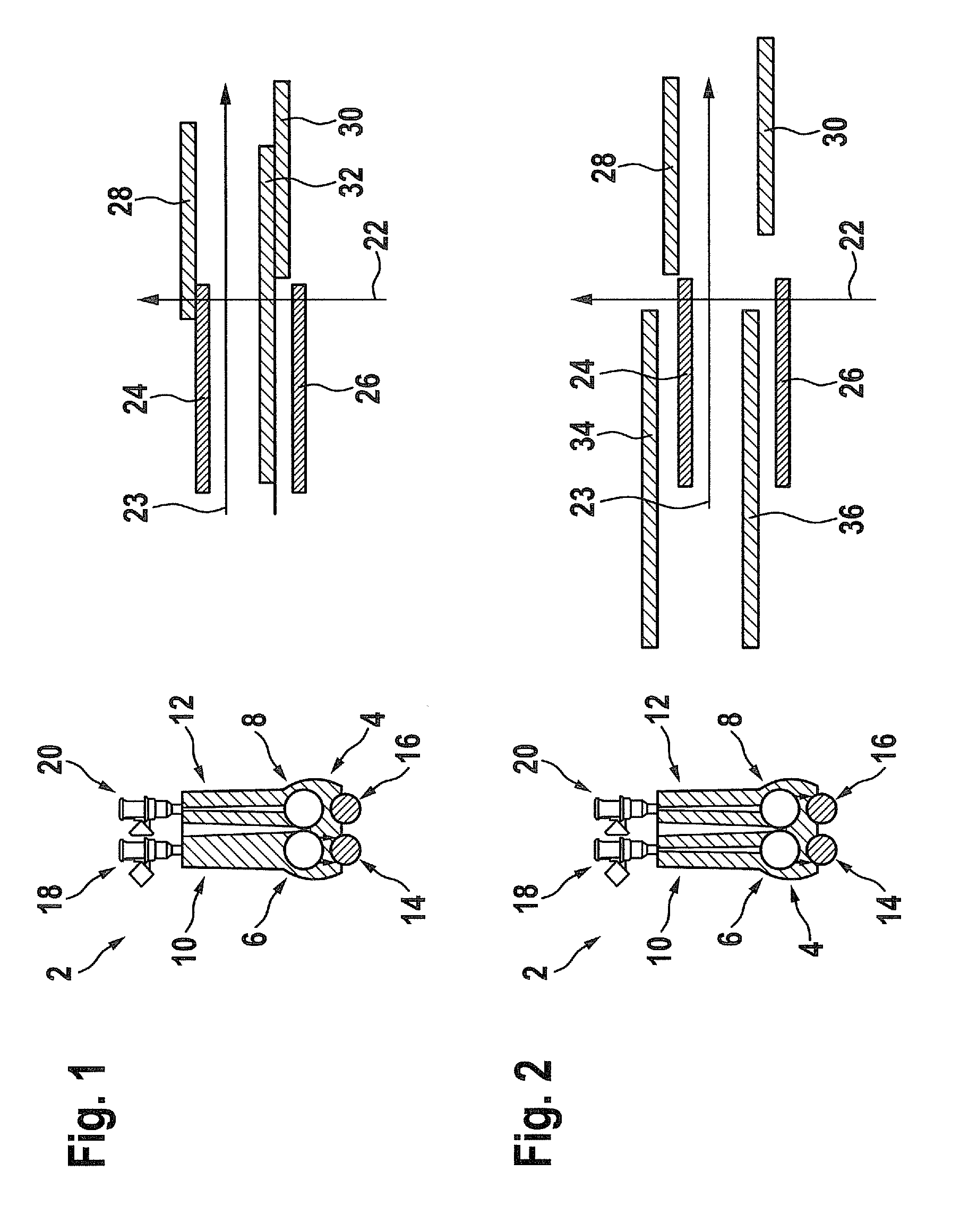
[0026]FIGS. 1 and 2 each show schematic representations of a detail of an internal combustion engine 2, which uses a known approach for employing the scavenging effect in SRE technology. The basis for the representation of this approach is to allow a comparison with the present invention described here.

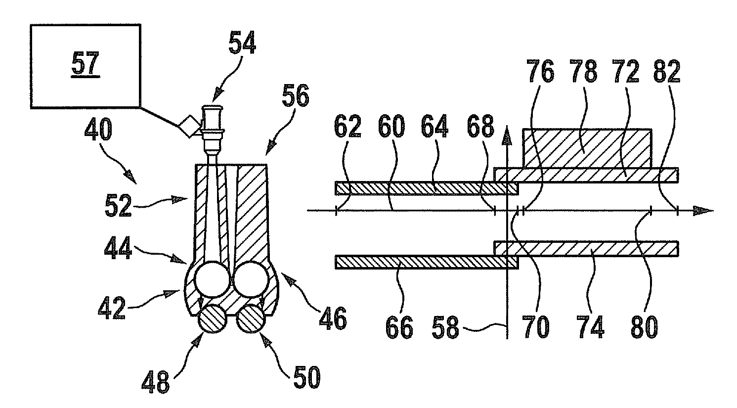
[0027]Internal combustion engine 2 includes a combustion chamber 4, which is connected via a first intake valve 6 and a second intake valve 8 to an intake port 10, 12. Furthermore, combustion chamber 4 is connected to two exhaust valves 14, 16. An injector 18, 20 is associated with each intake port 10, 12. Intake valves 6, 8 are controlled via a camshaft on which offset cams are installed, operating both intake valves 6, 8 with a time offset during operation. The intake control times are variable with the aid of a valve control during operation.

[0028]The two diagrams in each of FIGS. 1 and 2 include a vertically oriented axis 22, along which states of components of internal combustion...


PUM


Abstract

A method for performing an intake manifold injection for at least one combustion chamber of an internal combustion engine, at least one intake valve being connected to an intake port, at least one exhaust valve and at least one injector being assigned to at least one combustion chamber, fuel being injected into the at least one intake port by the at least one injector during an injection time, the injection time being started after the closing of the at least one exhaust valve and terminated before the closing of the at least one intake valve for performing the method.

Description

FIELD OF THE INVENTION[0001]The present invention relates to a method and an arrangement for performing an intake manifold injection.BACKGROUND INFORMATION[0002]So-called downsizing is used to reduce fuel consumption of a four-stroke gasoline engine, i.e., reducing displacement while maintaining the same performance data, typically the torque and / or the power. In order not to affect the power, either the maximum rotational speed or the relative air charge of the cylinders is increased with the aid of a crankshaft-driven compressor or an exhaust gas turbocharger.[0003]In the latter case, torque shortcomings are known to occur in the lower rotational speed range. A compromise is usually necessary to adapt a turbo machine to the engine because the torque in the lower rotational speed range differs from that of a naturally aspirated engine of a comparable power class. When an air flow rate during operation has reached a certain level, which depends on the design of the turbo machine, en...

Claims


Application Information

Patent Timeline
IPC IPC(8): F02M69/04
CPCF02D41/0002F02D41/0007F02D41/345Y02T10/42Y02T10/44Y02T10/144F02D2041/001F02D41/3094Y02T10/40Y02T10/12
Inventor LANG, AXELSAMENFINK, WOLFGANGKIEFFER, SEBASTIEN
Owner ROBERT BOSCH GMBH
Why Eureka
Try Eureka