Foldable, refillable, sustained-release fluid delivery system

a fluid delivery system and sustained release technology, applied in the direction of gaseous substances, insect catchers and killers, disinfection, etc., can solve the problems of missing a significant degree of volatilization, the emanator system used in these delivery devices and the known device lacks a secure retention system. , to achieve the effect of convenient handling and storag

Inactive Publication Date: 2005-12-01
MICROLIN
View PDF7 Cites 1 Cited by
  • Summary
  • Abstract
  • Description
  • Claims
  • Application Information

AI Technical Summary

Benefits of technology

[0031] The present invention is shown and described herein as a framed fluid delivery device that, at a minimum, has a fluid-delivery cartridge for the delivery of a fluid contained therein over a period of time, and a frame assembly for retaining the fluid delivery cartridge, comprising means for securing the fluid-delivery cartridge within the frame assembly. The frame enables the cartridge to be securely retained within the frame assembly for easy handling and storage.
[0032] Preferably, the frame assembly consists of a base portion having a means for facilitating the delivery of fluid released from the fluid-delivery cartridge, and at least one side panel, but preferably at least two side panels, associated with the base, wherein the securing means secures the fluid-delivery cartridge proximate the released fluid delivering means. The side panels may also have leg extensions depending therefrom. The side panels may be either hingedly or fixedly associated with the base portion. If the side panels are hingedly attached, they enable the frame assembly to begin from a substantially planar position and to be folded upward into its final shape or position.
[0036] In another preferred embodiment, the cartridge may be secured in the frame assembly using an aperture in the base portion of the frame assembly, in combination with one of the jaw members. Alternatively, an aperture could be used with a collar associated with the top of the frame assembly, or with a top portion of the frame assembly that has a concave arcuate shape. The collar is capable of securing the top of the cartridge by itself, while it is preferred that the top portion and the bottom portion include clips if the concave arcuate shape is used. In any case, the aperture, and indeed the collar, preferably includes interference pads to help secure the cartridge within the frame assembly through frictional forces.
[0043] The operation of the fluid delivery cartridge can be altered as needed so as to temporarily increase fluid delivery from the cartridge. To do so, in one preferred method, a user can (1) provide a fluid delivery device capable of delivering fluid over time, wherein the device contains a fluid to be delivered to a dispersion pad positioned proximate the fluid delivery device, (2) provide elements and / or structures for delivering a bolus of fluid, (3) can initiate the operation of the fluid delivery device, and then (4) activate the elements and / or structures for delivering a bolus to, in turn, deliver a bolus of fluid. For example, a user can activate the structures by pressing a button to increase the pressure within a fluid reservoir, breaking a breakable barrier of the fluid reservoir, or breaking the seal on a fluid impregnated sponge to, in turn, expose at least a portion of the sponge to ambient air. Alternatively, the cartridge could include a bolus reservoir that releases its contents into the outlet of the cartridge upon application of pressure. Any of these methods can be utilized to increase the immediate fluid flow of the cartridge.

Problems solved by technology

These known devices, however, have several drawbacks.
The cartridges and emanator systems used in these delivery devices lack a secure retention system that would enable these devices to be placed in a variety of housings and to be easily handled during use.
Further, as the currently-known devices retain the released liquid solely below the cartridge, a significant degree of improved volatilization is being missed.
Finally, the regulation of the operation of the device, both in initiation and in continued operation, has not, as of yet, been addressed to a significant degree.

Method used


Image

  • Foldable, refillable, sustained-release fluid delivery system
  • Foldable, refillable, sustained-release fluid delivery system
  • Foldable, refillable, sustained-release fluid delivery system

Examples


second embodiment

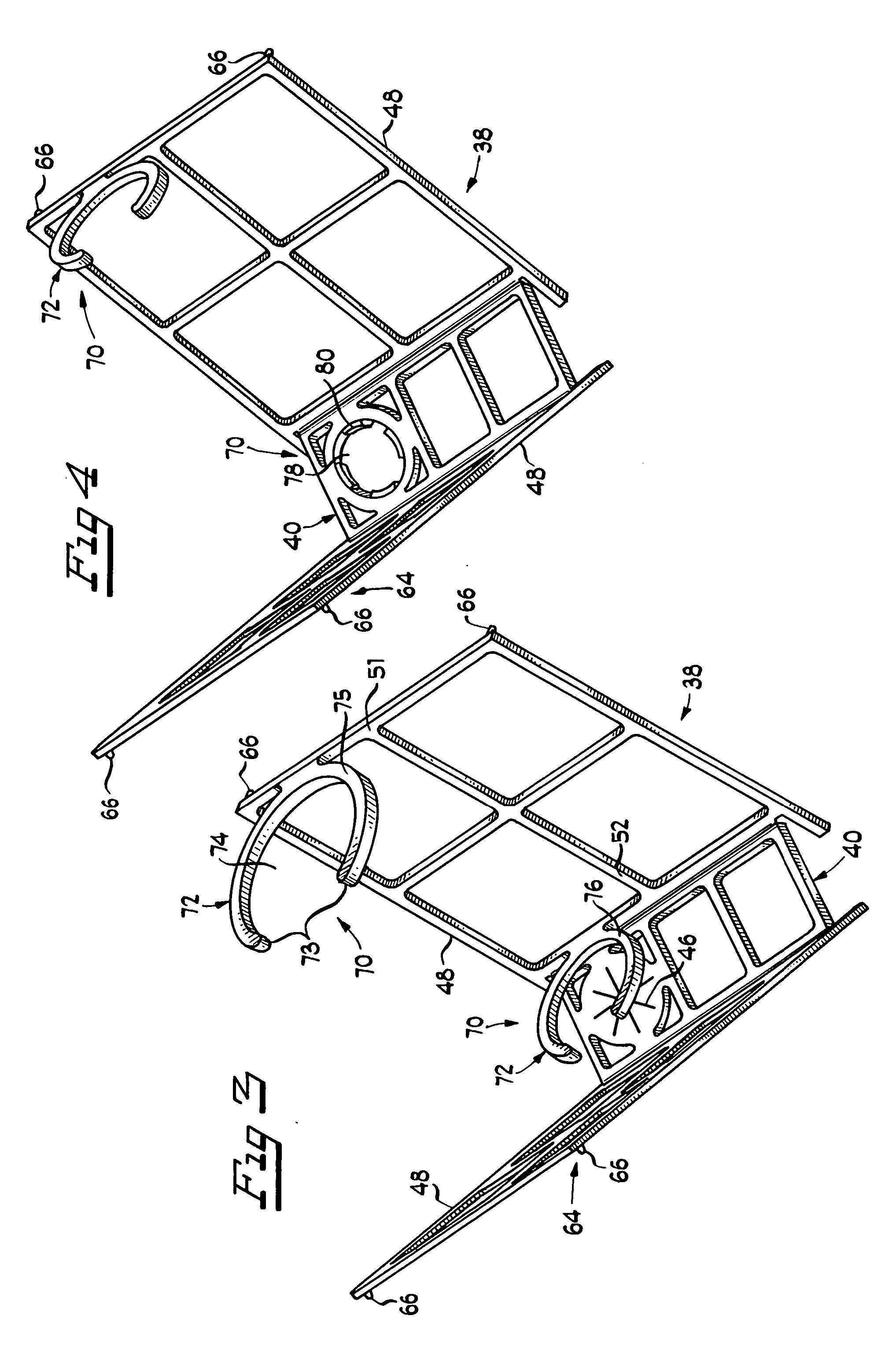
[0075] the cartridge securing means 70 is shown in FIG. 3 as comprising a snap and lock apparatus having at least two jaw members 72 that are capable of releasably securing cartridge 12 within frame assembly 38. Jaw members 72 comprise a resilient, semi-rigid material, such as plastic and the like, which is formed into a semi-circular shape approximating the diameter / shape of cartridge 12. Tips 73 ofjaw member 72 flex outward upon contact with cartridge 12, allowing cartridge 12 to pass into interior 74 ofjaw member 72. Thereafter, tips 73 flex back into the original position, securing cartridge 12 therein.

[0076] Preferably, at least two jaw members 72 are molded into or associated with one or more of side panels 48. In one preferred embodiment, jaw members 72 comprise a top 75 and a bottom 76 jaw member attached to top 51 and bottom 52 portions of a single side panel 48 respectively. Alternatively, depending upon the specific shape of base portion 40, and thus the overall shape of ...

third embodiment

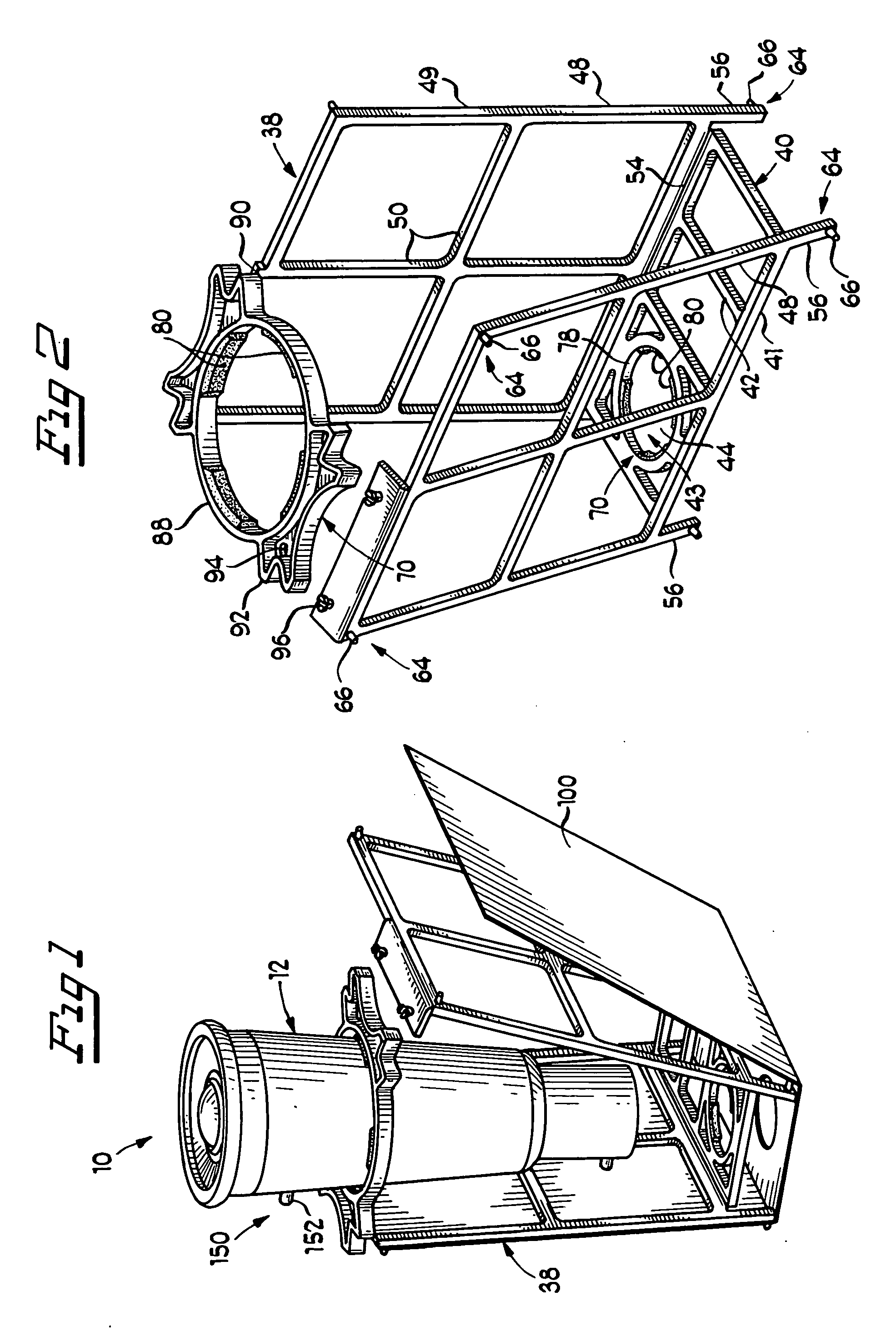
[0077] the cartridge securing means 70 is shown in FIG. 4 as a combination of the snap and locking jaw members 72, and an aperture 78 within base portion 40. In this embodiment, after fluid-delivery cartridge 12 is inserted into aperture 78, securing the bottom of cartridge 12 therein, the top portion of cartridge 12 may be secured also using jaw member 72. Depending upon the nature of frame assembly 38 (folding or non-folding), cartridge 12 may be secured by jaw member 72 upon insertion into aperture 78, or may be secured after insertion into aperture 78 by folding frame assembly 38 together. As with the embodiment shown in FIG. 2, it is preferred that aperture 78 additionally includes interference pads 80 for frictionally securing cartridge 12 therein.

fourth embodiment

[0078] cartridge securing means 70 is shown in FIG. 5. In that embodiment, frame assembly 38 additionally includes top portion 58, which at least partially covers and spans across the top of frame assembly 38, and is associated with side panels 48 using any one of the above-discussed means (molding, hinging, snap pin hole / snap fit pin, etc.). Top portion 58 preferably has a convex, arcuate shape, wherein the middle of the arcuate shape approximately coincides with fluid delivery facilitating means 43 of base portion 40. Facilitating means 43 preferably comprises aperture 78, but may additionally comprise scored slits 46, as discussed above. Cartridge 12 is placed at the middle of the arcuate shape, and over facilitating means, and is secured there using clip members 82.

[0079] A top clip member 84 is secured to the arcuate shape of top portion, and secures the top of cartridge 12 thereto. A bottom clip member 86 is secured to base portion 40, and further secures bottom of cartridge 1...


PUM

PropertyMeasurementUnit
pressureaaaaaaaaaa
volatileaaaaaaaaaa
timeaaaaaaaaaa

Abstract

The invention described herein is a framed fluid delivery device that is made up of a fluid-delivery cartridge for the timed-release delivery of a fluid contained therein, and a frame assembly for retaining the fluid delivery cartridge. The frame assembly is made up of a base portion that facilitates the delivery of fluid released from the fluid-delivery cartridge, at least one side panel associated with the base, and that secures the fluid-delivery cartridge within the frame assembly proximate the released fluid delivering means. Additionally, a fluid delivery device is disclosed that includes a fluid-delivery cartridge for the timed-release delivery of a fluid contained therein, the cartridge having a bottom, a top, and sides, and a dispersion pad positioned proximate the bottom of the fluid-delivery cartridge, wherein the dispersion pad at least partially surrounds the sides of the fluid-delivery cartridge.

Description

RELATED APPLICATIONS [0001] This is a divisional patent application claiming benefit to U.S. patent application Ser. No. 10 / 300,729 filed on Nov. 20, 2002; the content of which is incorporated by reference herein.BACKGROUND OF THE INVENTION [0002] 1. Field of the Invention [0003] The present invention relates generally to the delivery of volatile liquids over a period of time to a surrounding area of space, and particularly to structures capable of retaining a fluid delivery device capable of releasing a fluid over time, and facilitating the improved release of volatile liquids therefrom. [0004] 2. Background Art [0005] The need for the sustained-release of volatile fluids has been known for some time. In particular, a number of industries have focused on new and innovative ways to provide improved structures for the delivery of known volatile substances. For example, air freshening agents and insecticides have been delivered over a long period of time using devices such as plug-in ...

Claims


Application Information

Patent Timeline
Patent Type & Authority Applications(United States)
IPC IPC(8): A61L9/04
CPCA01M1/2044A61L9/04A61L9/042A61L9/127
Inventor JOSHI, ASHOKWOLD, TRUMANMCEVOY, JOHN
Owner MICROLIN
Why Eureka
Try Eureka