

Color filter, color image display device, and electronic apparatus
- Summary
- Abstract
- Description
- Claims
- Application Information
AI Technical Summary
Benefits of technology
Problems solved by technology
Method used
Image

Examples
first embodiment
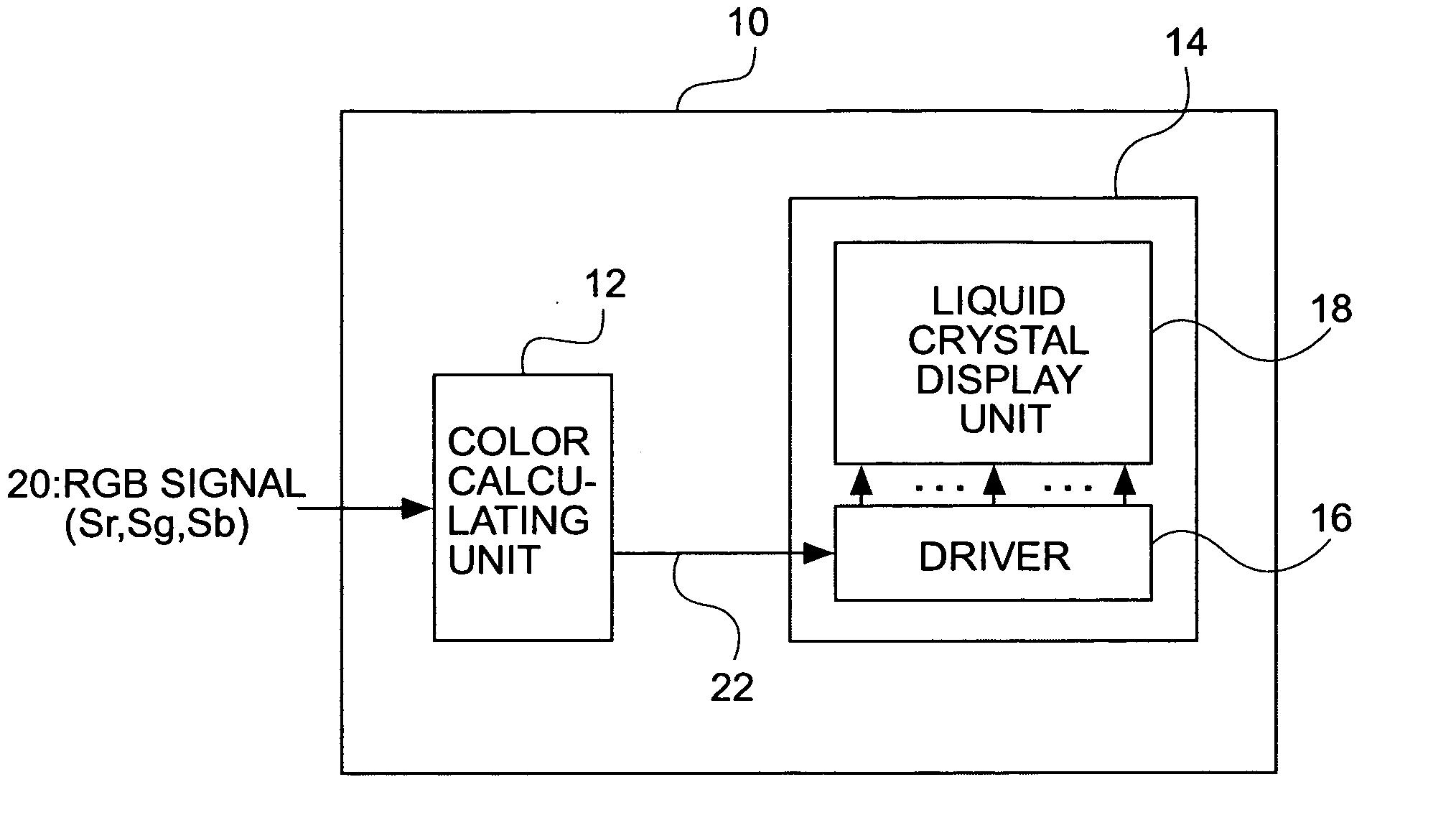
[0060] Next, a first embodiment of a display device to which the six-color filter is applied will be described. FIG. 4 shows a configuration of a display device 10 according to the first embodiment. The display device 10 is applicable to mobile terminals of PDAs and so on. In FIG. 4, the display device 10 according to the first embodiment has a color calculating unit 12 and a liquid crystal display panel 14. The liquid crystal display panel 14 has a liquid crystal display unit 18 and a driver 16.
[0061] The display device 10 receives an RGB signal 20 from the exterior. The RGB signal includes an R signal Sr, a G signal Sg, and a B signal Sb. The color calculating unit 12 generates six color signals 22 from the received RGB signal. The six color signals 22 correspond to R, G, B, YL, M, and C colors, respectively, and are supplied to the driver 16 in the liquid crystal display panel 14.
[0062] The liquid crystal display unit 18 is a liquid crystal display unit to which the six-color f...
second embodiment
[0067] Next, a second embodiment of the display device will be described. FIG. 6 shows a configuration of a display device 10a according to the second embodiment. In the display device 10 shown in FIG. 4, when the RGB signal 20 is input, the six color signals are generated based on the RGB signal 20 and an image is displayed on the liquid crystal display panel 14 on which the six-color filter is mounted. In the second embodiment, the display device 10a is constituted such that the YMC signal 24 also is input thereto. That is, when the source image is input as the RGB signal 20, like the display device 10, the display device 10a generates the six color signals from the RGB signal 20 and provides them to the liquid crystal display panel 14. When the source image is input as the YMC signal 24, a color calculating unit 12a generates the six color signals 26 from the YMC signal 24 and provides them to the liquid crystal display panel 14.
[0068] When the YMC signal 24 is input, the color ...
third embodiment
[0071] Next, a third embodiment of the display device will be described. FIG. 8 shows a configuration of a display device 10b according to the third embodiment. Like the display device 10 according to the first embodiment, the RGB signal is input as an input signal. However, in the third embodiment, a color calculating unit 12b generates the six color signals 28 with a different method from the method in the first embodiment and output them.
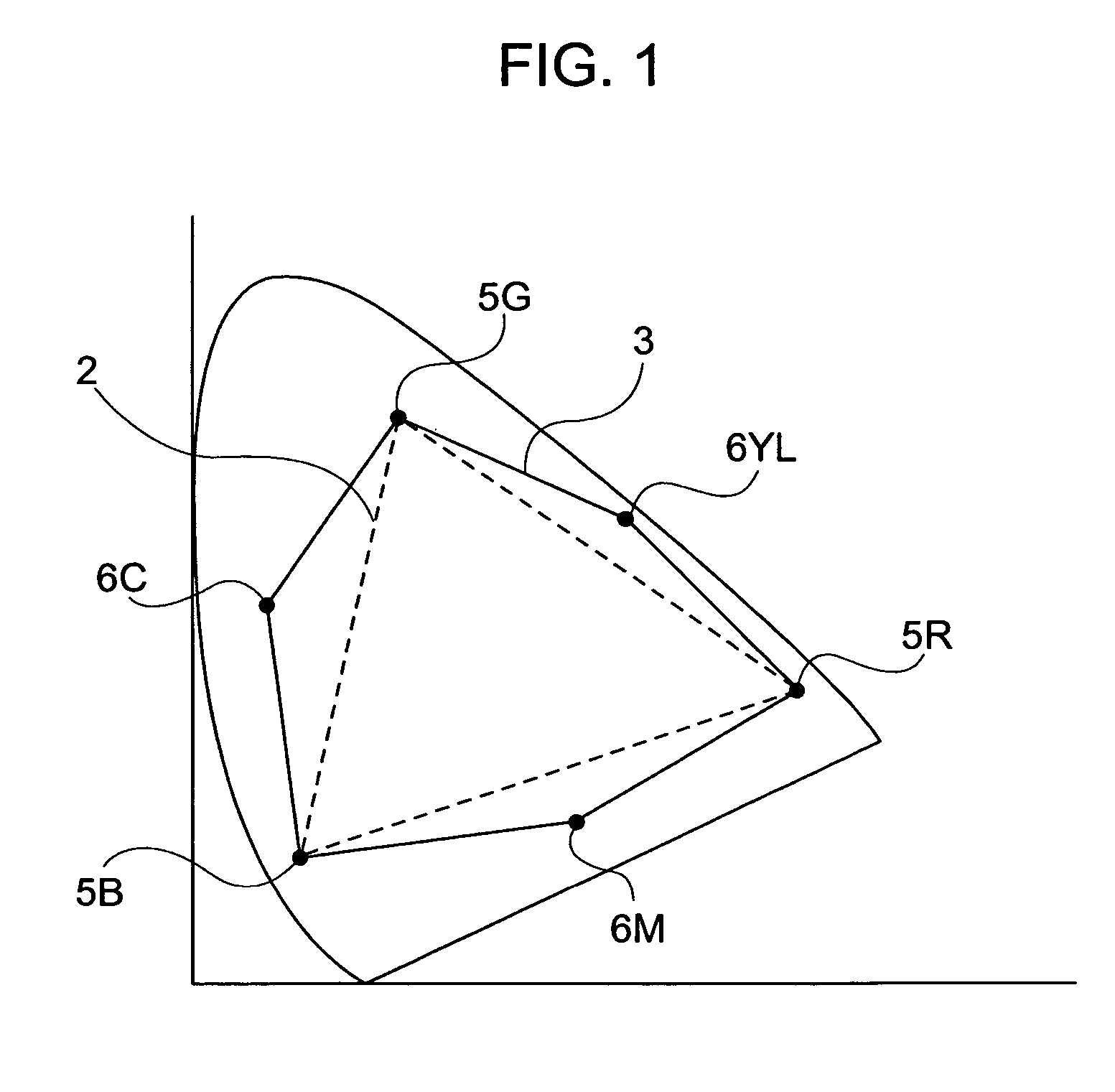
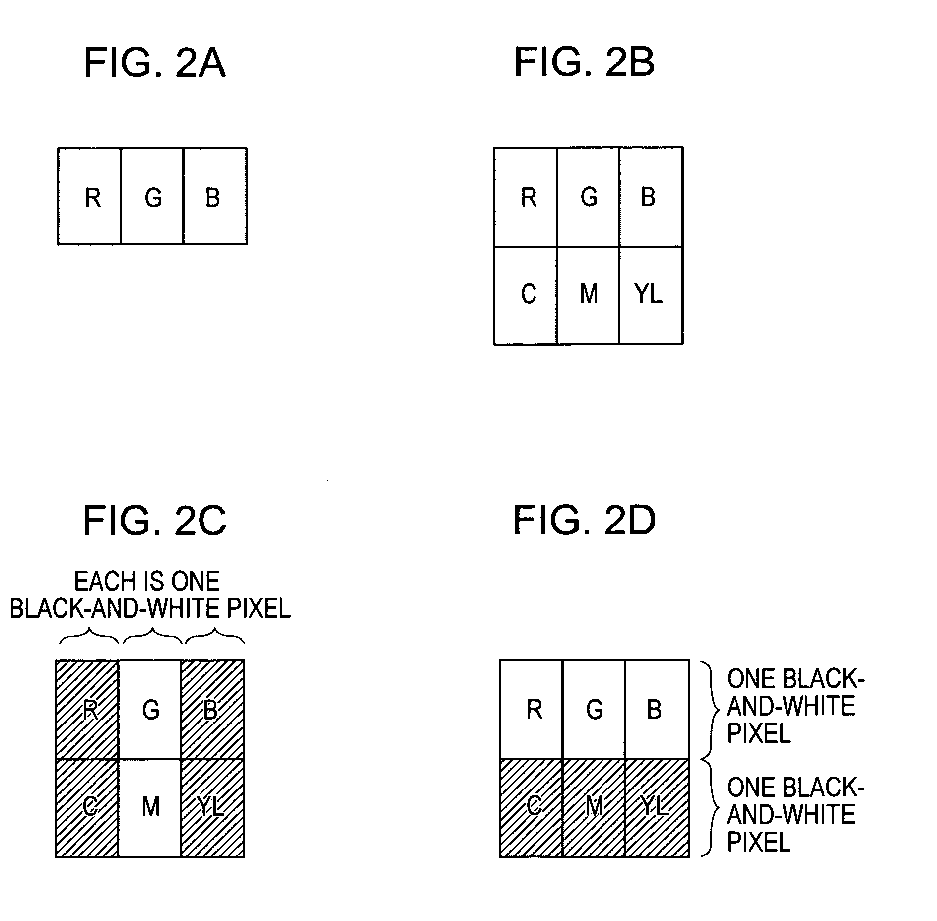
[0072] As described above, the six-color filter according to the invention has a wide color reproduction region with regard to a color image signal as compared to the general RGB color filter. Meanwhile, since six-color pixels constitute one color pixel, the resolution is deteriorated. In a case of the black-and-white image, it is possible to compensate for the deterioration of resolution by the arrangement of the six colors as described above.
[0073] According to features of the third embodiment, it is determined whether an input image is a bla...
PUM
 Abstract
Description
Claims
Application Information