Selecting clock frequencies for baseband devices

a baseband device and clock frequency technology, applied in the field of integrated circuits, can solve problems such as the potential for interference between analog and digital components

Active Publication Date: 2005-12-01
SILICON LAB INC
View PDF9 Cites 67 Cited by
  • Summary
  • Abstract
  • Description
  • Claims
  • Application Information

AI Technical Summary

Benefits of technology

[0008] One aspect of the present invention includes a method of adjusting a clock frequency for a baseband component of a system to avoid interference with a RF signal, such as a signal channel or a local oscillator (LO) frequency used by a receiver of the system.
[0009] Another aspect of the present invention includes a method of receiving a RF signal spectrum in a receiver; mixing the RF signal spectrum with a first LO frequency to obtain a first downmixed signal; and converting the first downmixed signal to a first digital signal using an analog-to-digital converter (ADC) having an adjustable clock frequency selected to avoid interference with the first LO frequency.

Problems solved by technology

Because of the presence of both analog and digital circuitry within such IC devices, there is a potential for interference between the analog and digital components.
While various sources of such interference may exist, one particular source of interference may be interference caused by harmonics of baseband clock frequencies that interfere with RF frequencies within the IC device.

Method used


Image

  • Selecting clock frequencies for baseband devices
  • Selecting clock frequencies for baseband devices
  • Selecting clock frequencies for baseband devices

Examples


Embodiment Construction

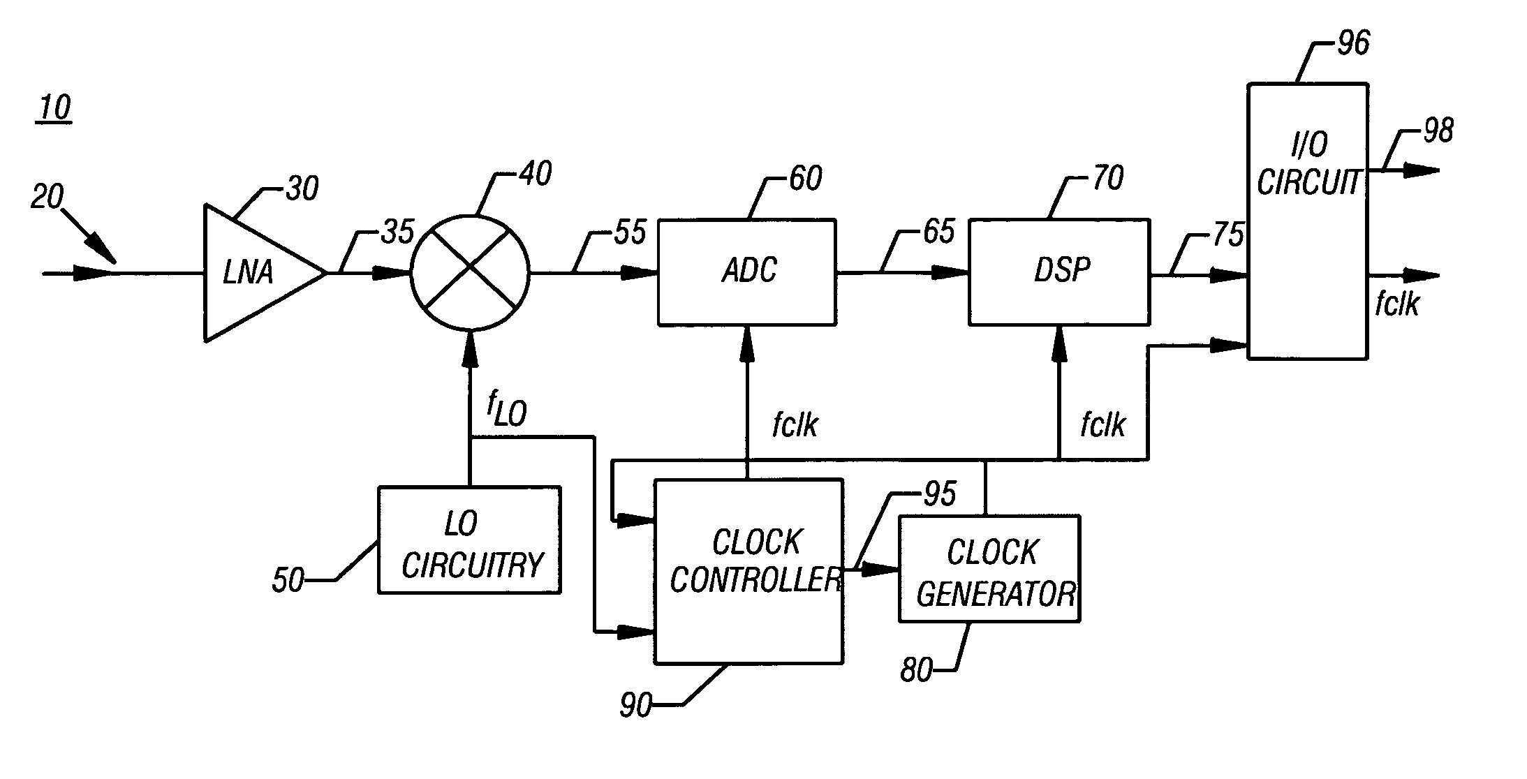
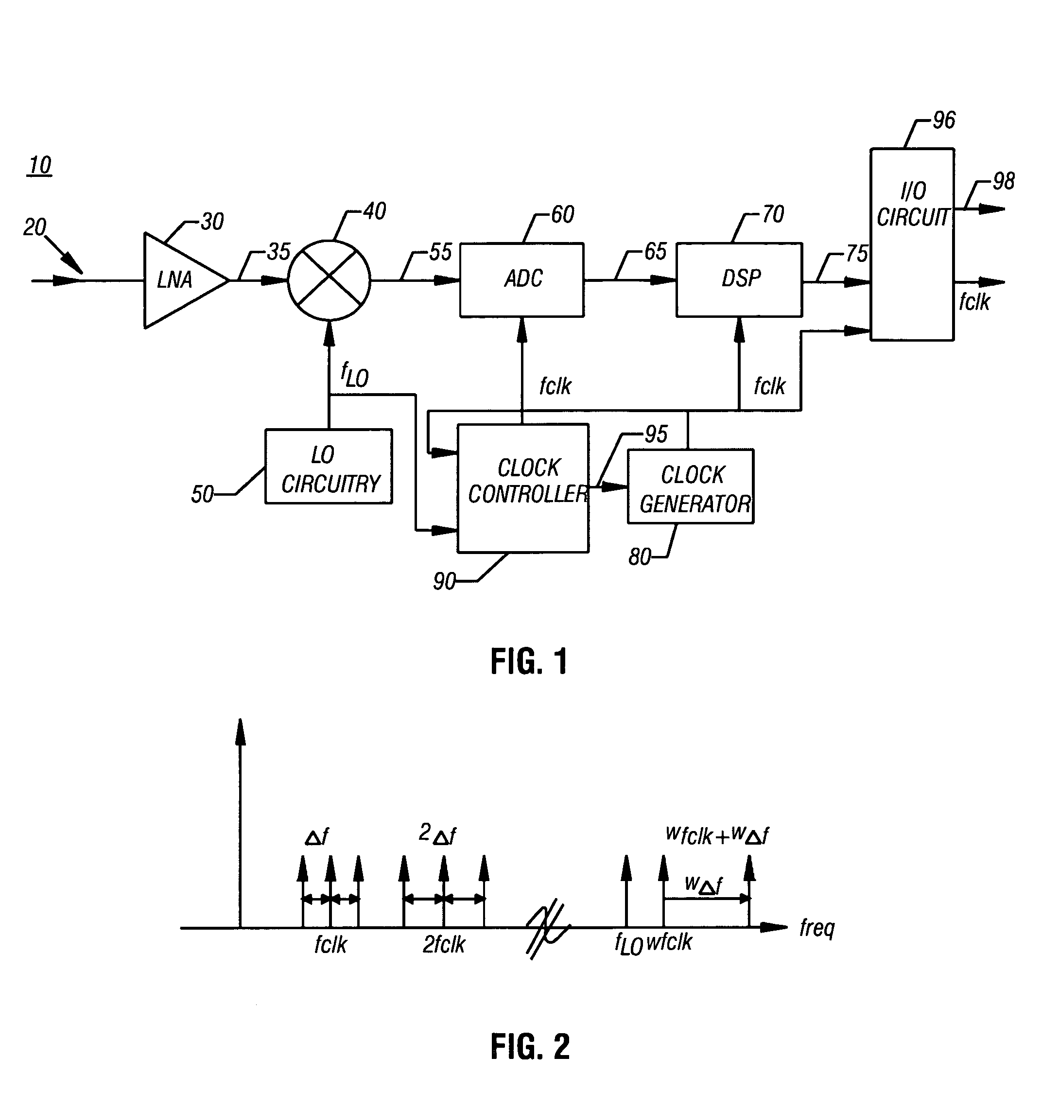
[0011] Referring to FIG. 1, shown is a block diagram of a system in accordance with one embodiment of the present invention. As shown in FIG. 1, system 10 may be, for example, a receiver for use in a RF system such as a satellite receiver for use in a set-top box or other television tuner. While discussed primarily herein as used in such a satellite system, it is to be understood that other embodiments of the present invention may be used in connection with other RF systems, such as cellular telephones, radios, other communication systems and the like.

[0012] As shown in FIG. 1, system 10 receives an incoming signal 20 at a low noise amplifier (LNA) 30. The resulting amplified signal 35 may then be input into a mixer 40, where the RF signal is mixed with a local oscillator (LO) frequency (fLO) provided by LO circuitry 50.

[0013] The resulting downconverted signal 55 may be provided to baseband circuitry for further processing. For example, downconverted signal 55 may be sent to an a...


PUM


Abstract

Various embodiments of the present invention include methods and apparatus for receiving a radio frequency (RF) signal spectrum in a receiver; mixing the RF signal spectrum with a first local oscillator (LO) frequency to obtain a first downmixed signal; and converting the first downmixed signal to a first digital signal using an analog-to-digital converter (ADC) having an adjustable clock frequency selected to avoid interference with the first LO frequency. The adjustable clock frequency may be adjusted by a predetermined amount, by phase modulation, or in other manners.

Description

TECHNICAL FIELD OF THE INVENTION [0001] The invention relates to integrated circuits, and more specifically to avoiding interference between different components within such circuits. BACKGROUND [0002] Numerous integrated circuits (IC) are used for mixed signal purposes. That is, such circuits include both analog and digital components. Specifically, certain such mixed signal circuits include analog circuitry that operates at extremely high frequencies, for example, radio frequencies (RF), and digital circuitry that operates at baseband frequencies. Because of the presence of both analog and digital circuitry within such IC devices, there is a potential for interference between the analog and digital components. [0003] While various sources of such interference may exist, one particular source of interference may be interference caused by harmonics of baseband clock frequencies that interfere with RF frequencies within the IC device. Accordingly, a need exists to reduce or prevent s...

Claims


Application Information

Patent Timeline
Patent Type & Authority Applications(United States)
IPC IPC(8): H04B15/06H04L27/22
CPCH04B15/06
Inventor CRAWLEY, PHILIP
Owner SILICON LAB INC
Why Eureka
Try Eureka