Eureka AIR delivers breakthrough ideas for toughest innovation challenges, trusted by R&D personnel around the world.

Load port for clean system

a clean system and port technology, applied in the field of port, can solve the problems of affecting the air flow between the space, affecting the clean environment, dust, dust and the like, and reducing the possibility of pollution in the clean environmen

Inactive Publication Date: 2005-12-01
TDK CORPARATION
View PDF12 Cites 7 Cited by
  • Summary
  • Abstract
  • Description
  • Claims
  • Application Information

AI Technical Summary

Benefits of technology

[0010] The present invention has been achieved in view of the above-described state of affairs, and is aimed to provide the FOUP for reducing the

Problems solved by technology

Therefore, when the door removes the FOUP's lid from its main body, two or three space in which a pressure difference exists are to be connected together in one stroke, resulting in an abrupt air flow between these space.
Such air flow may pos

Method used


Image

  • Load port for clean system
  • Load port for clean system
  • Load port for clean system

Examples


Embodiment Construction

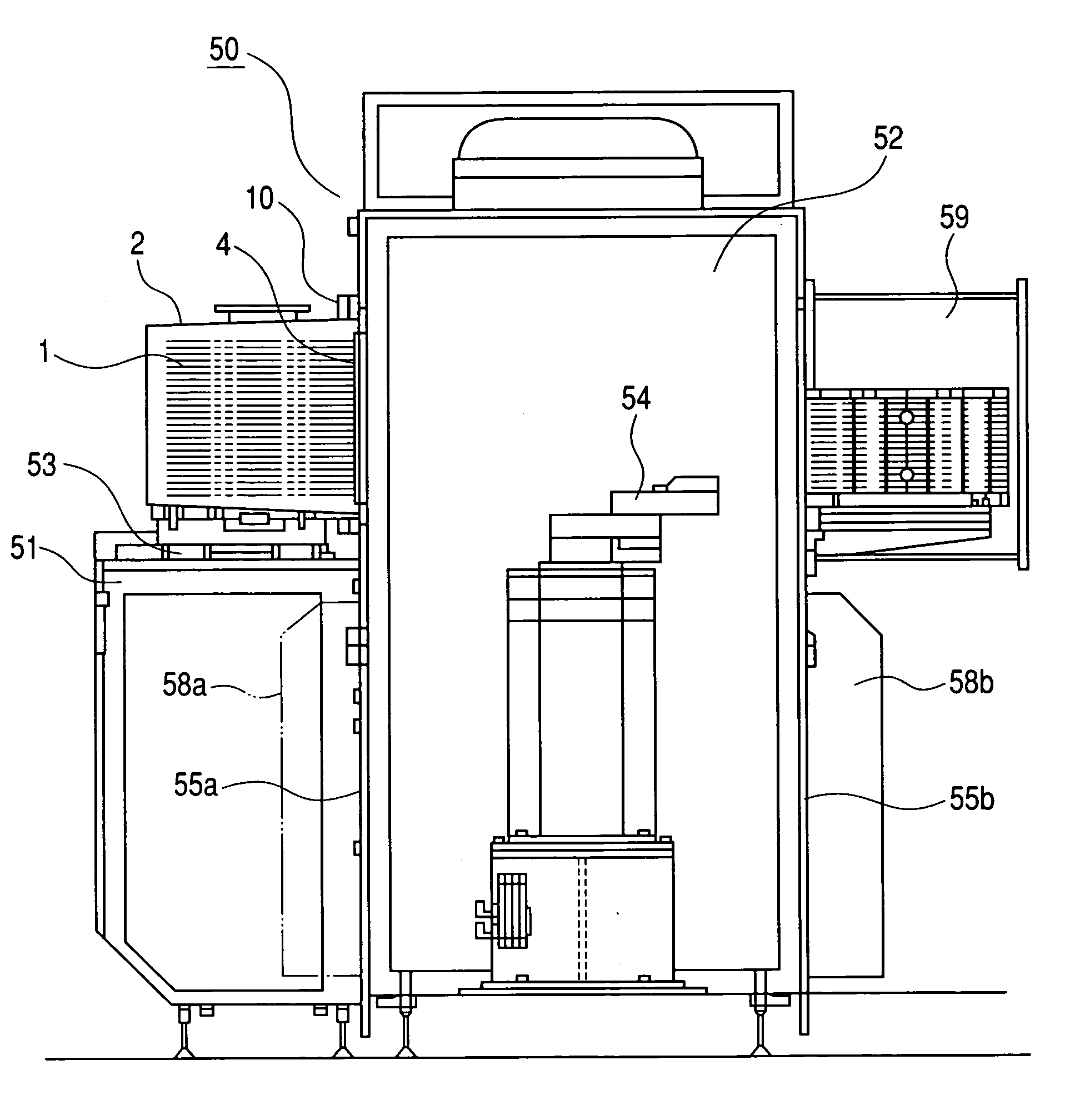
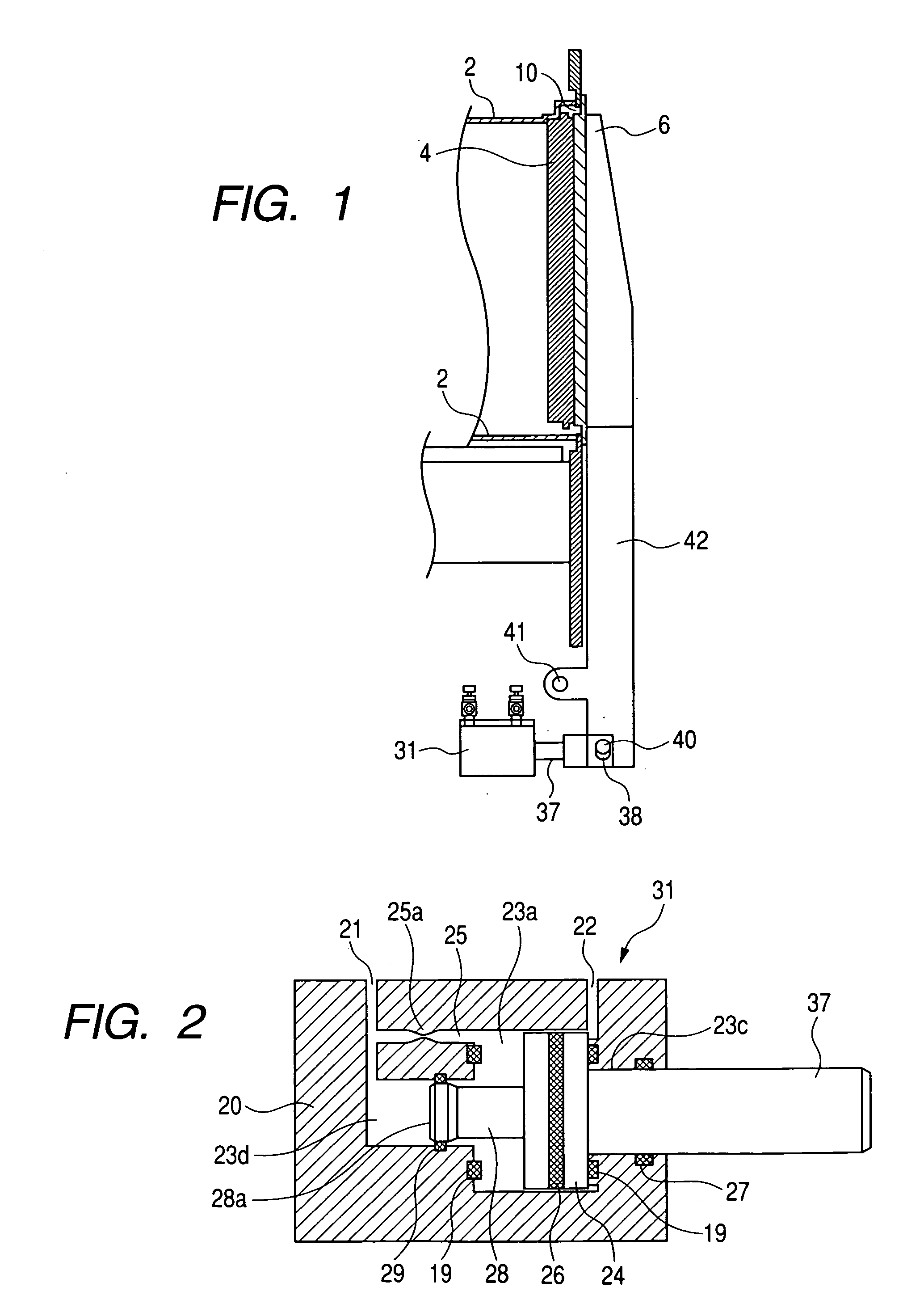
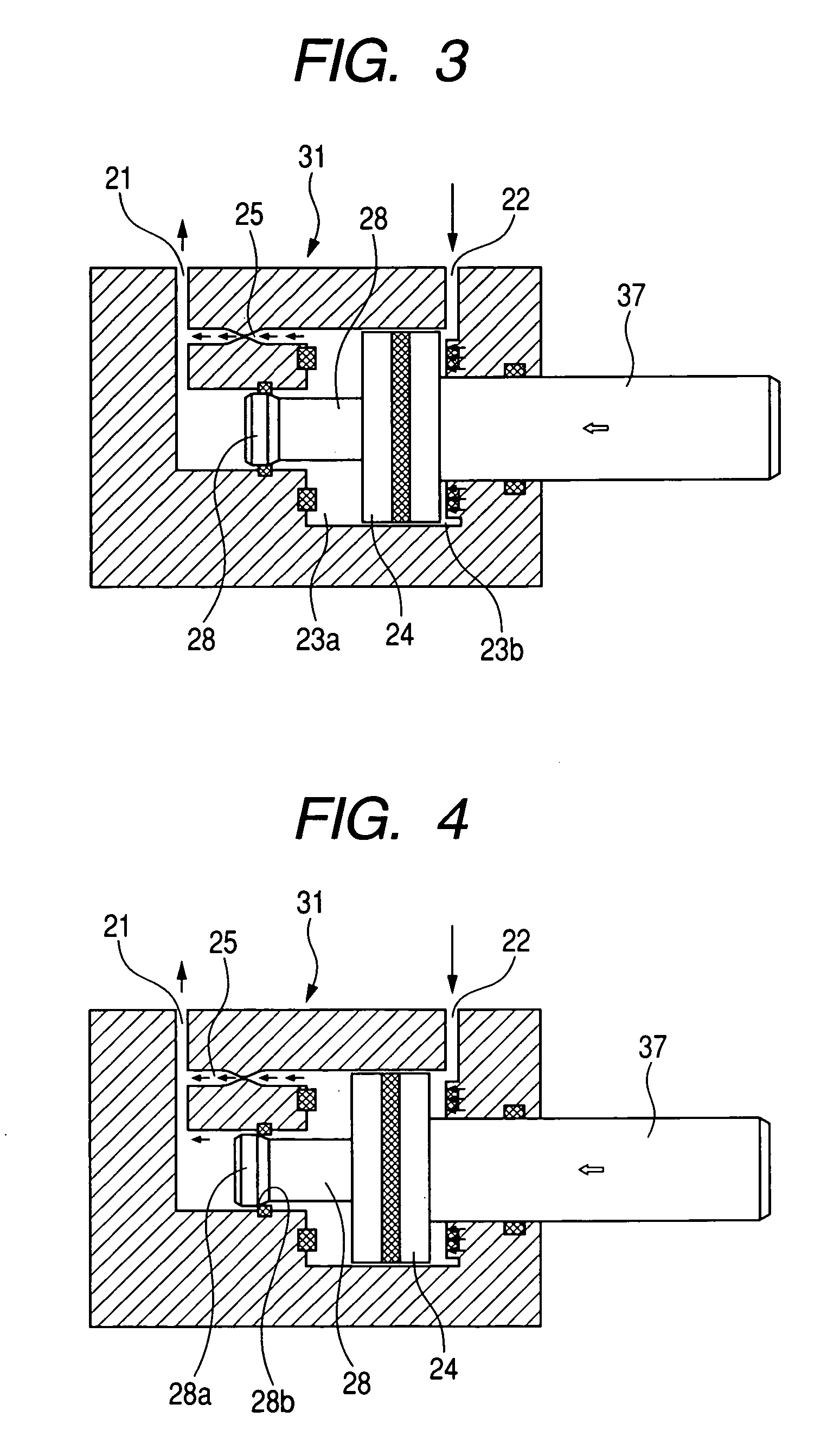
[0024] Hereinafter, with reference to the drawings, the description will be made of a load port according to an embodiment of the present invention. FIG. 1 is a side view showing a part of FOUP, a door in a FIMS system and a principal part of its open and close mechanism. Also, FIG. 2 shows the schematic structure of a cross section of a two-step cylinder, which is a drive unit for actually opening and closing the door in the system concerned. In more detail, FIG. 1 shows that the first aperture of the load port has been closed by the door and a state in which the FOUP in a lid-closed state has come into contact with the door.

[0025] In FIG. 1, the main body 2 of FOUP has its aperture closed by a lid 4. A door 6 is supported by a door arm 42, and a first aperture 10 in the FIMS system has been closed in the state shown in FIG. 1. On a door 6-side surface of the lid 4 and the lid 4-side surface of the door 6, there has been arranged a restraining mechanism (not shown) for shifting th...


PUM


Abstract

The present invention is aimed to reduce a possibility that clean space at the so-called door being opened in the FIMS system is polluted. In order to achieve the object concerned, as a driving mechanism for driving a load port door in the FIMS system, mechanisms different in driving speed are used between during the early stage of driving and any other state than it. Particularly, during the early stage of driving, it is made possible to drive the door at exceedingly low speed, and after the door is opened by a predetermined amount, the door will be driven at high speed that has been usually controlled.

Description

BACKGROUND OF THE INVENTION [0001] 1. Field of the Invention [0002] The present invention relates to a so-called load port for forming, in a manufacturing process for an object such as semiconductors, flat-panel display panels and optical disks, in which under a highly clean environment their process is performed, clean space for carrying the object or the like in to or out of an object housing container for housing the object or the like, and more particularly to a port door for opening or closing a lid for closing an aperture in the main body of the housing container concerned as well as opening or closing the clean space. [0003] 2. Related Background Art [0004] In the past, the semiconductor manufacturing process was performed within a so-called clean room obtained by making the interior of a chamber for handling semiconductor wafers highly clean. However, in terms of the tendency of wafer size toward bulkiness and reduction in cost required for management of the clean room, in r...

Claims


Application Information

Patent Timeline
IPC IPC(8): B65G65/34H01L21/677H01L21/68
CPCH01L21/67772
Inventor SUZUKI, HITOSHIOKABE, TSUTOMUIGARASHI, HIROSHI
Owner TDK CORPARATION
Why Eureka
Eureka Blog
Learn More