

Housing for axial flow heat-dissipating fan
a technology of axial flow and heat dissipation fan, which is applied in the direction of mechanical actuators, machines/engines, liquid fuel engines, etc., can solve the problems of reducing the air pressurizing effect in the housing, failing to provide the expected blowing efficiency, and affecting the air output, so as to reduce the noise of blowing, increase the air inlet efficiency, and improve the effect of air outlet efficiency
- Summary
- Abstract
- Description
- Claims
- Application Information
AI Technical Summary
Benefits of technology
Problems solved by technology
Method used
Image

Examples
first embodiment
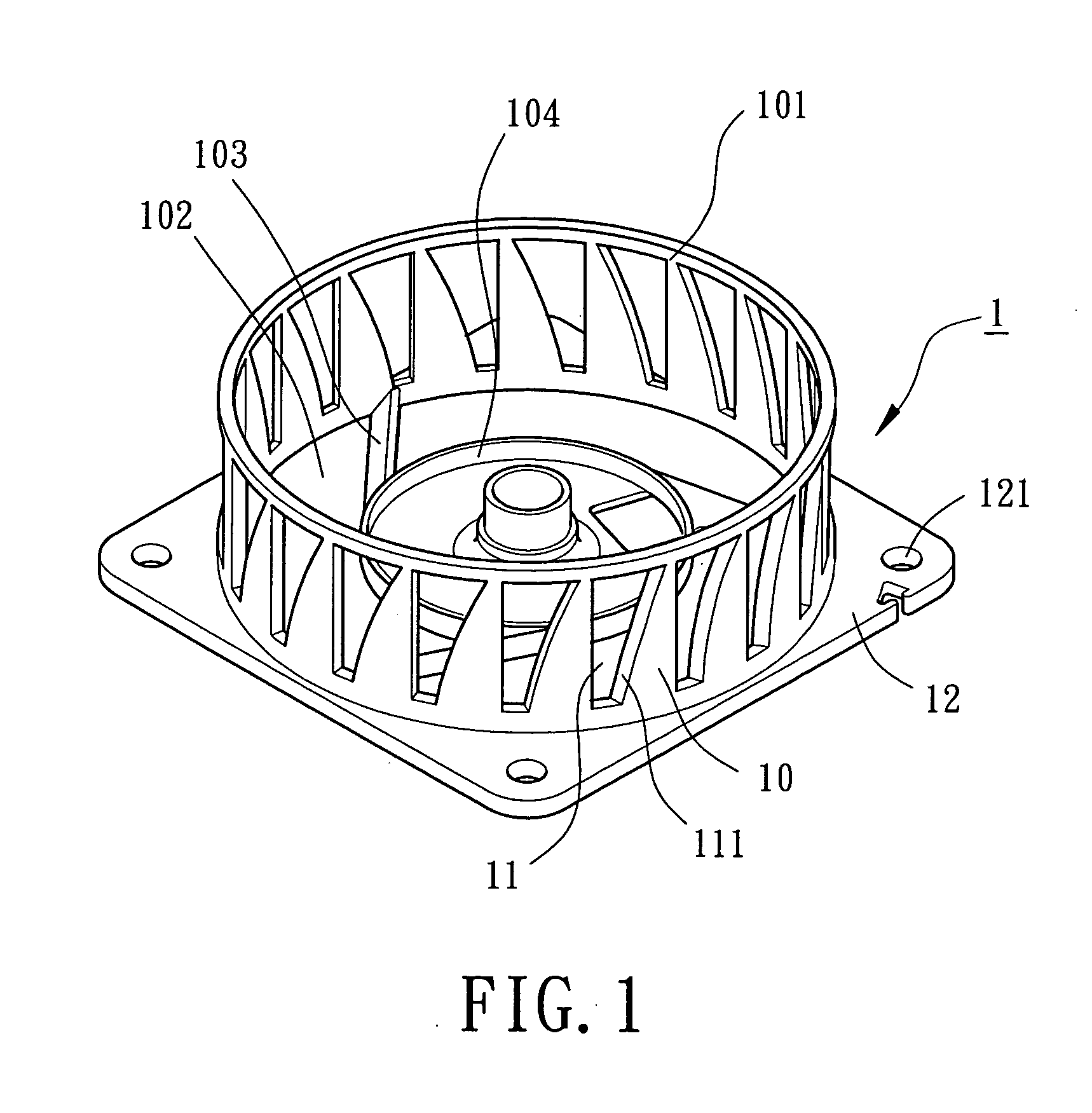
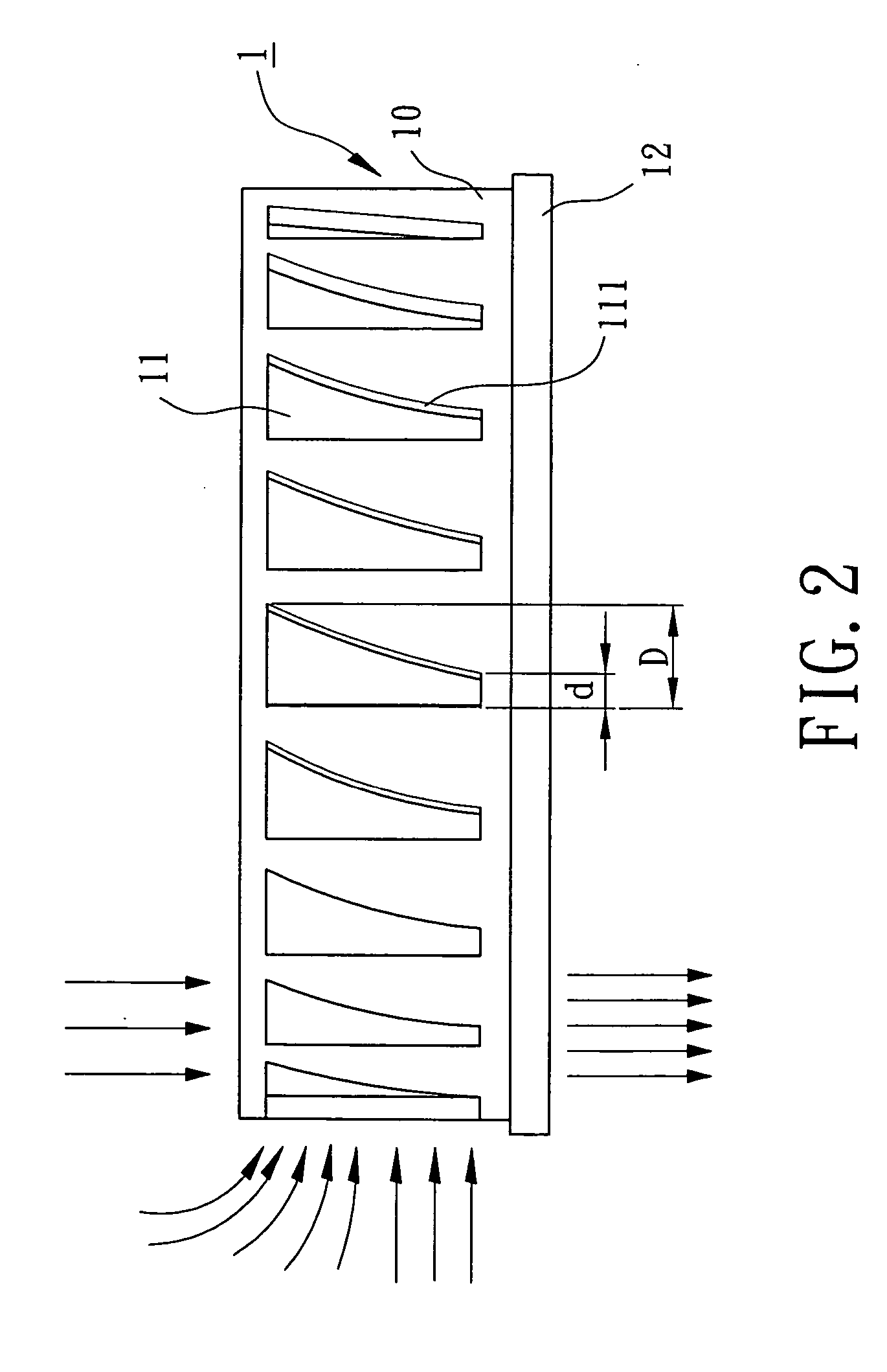
[0024]FIG. 1 is a perspective view of a housing for an axial flow heat-dissipating fan in accordance with the present invention. FIG. 2 is a side view of the housing in FIG. 1.
[0025] The housing 1 for an axial flow heat-dissipating fan in accordance with the present invention comprises an annular wall 10 that is substantially circular when viewed in section. The annular wall 10 includes an air inlet 101 in an end thereof and an air outlet 102 in the other end thereof. A base 104 is mounted in the air outlet 102 and supported by a plurality of ribs 103 between the base 104 and the annular wall 10. A motor (not shown) of an axial flow heat-dissipating fan is mounted to the base 104.
[0026] The annular wall 10 further includes a plurality of axially extending slits 11 equispaced along a circumference of the annular wall 10 for drawing ambient air surrounding the annular wall 10. Preferably, a width of each axially extending slit 11 increases from a first end thereof adjacent to the air...
second embodiment
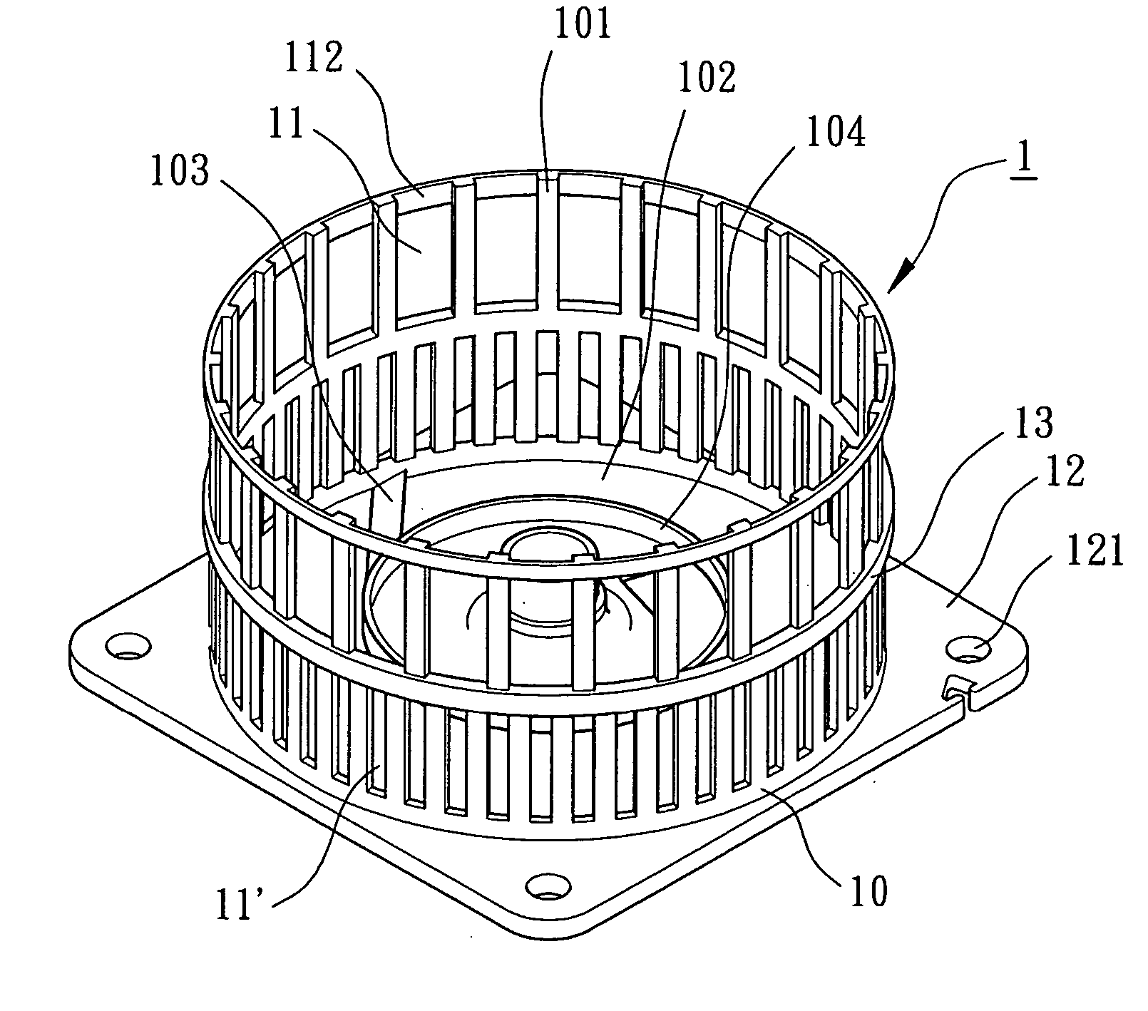
[0028]FIGS. 3 and 4 illustrate the housing 1 in accordance with the present invention. In this embodiment, the annular wall 10 of the housing 1 includes a first set of axially extending slits 11 adjacent to the air inlet 101 of the housing 1 and a second set of axially extending slits 11′ adjacent to the air outlet 102 of the housing 1. Each of the first set of axially extending slit 11 includes an end 111 extending through an end face of the annular wall 10 and communicated with the air inlet 101. Each of the second set of axially extending slits 11′ has a width d smaller than that D of each of the first set of axially extending slits 11. Further, a reinforcing rib 13 is located between the first set of axially extending slits 11 and the second set of axially extending slits 11′ and extends along the circumference of the annular wall 10. The reinforcing rib 13 reinforces the structure of the annular wall 10 with axially extending slits 11 and 11′. The overall air inlet amount is in...
third embodiment
[0029]FIG. 5 illustrates the housing 1 in accordance with the present invention. In this embodiment, the annular wall 10 of the housing 1 includes a first set of axially extending slits 11 adjacent to the air inlet 101 of the housing 1, a second set of axially extending slits 11″ adjacent to the air outlet 102 of the housing 1, and a third set of axially extending slits 11′ between the first set of axially extending slits 11 and the second set of axially extending slits 11″. Each of the second set of axially extending slits 11″ has a width smaller than that of each of the third set of axially extending slits 11′, which, in turn, smaller than that of each of the first set of axially extending slits 11. Further, a reinforcing rib 13 is located between the first set of axially extending slits 11 and the third set of axially extending slits 11′ and extends along the circumference of the annular wall 10. Similarly, a reinforcing rib 13′ is located between the third set of axially extendi...
PUM
 Abstract
Description
Claims
Application Information