Endoscope

a technology of endoscope and endoscope, which is applied in the field of endoscope, can solve the problems of difficult control of the movement of the treatment tool, difficult to precisely position the treatment section, etc., and achieve the effect of simplifying the device structur

Inactive Publication Date: 2005-12-01
OLYMPUS CORP
View PDF12 Cites 70 Cited by
  • Summary
  • Abstract
  • Description
  • Claims
  • Application Information

AI Technical Summary

Benefits of technology

[0011] According to the present invention, since the position of the distal portion of the treatment tool can be fine-adjusted, it is easy to accurately position the distal portion of the treatment tool with respect to the subject to be treated. The treatment tool insertion / withdrawal mechanism is preferably configured to move the treatment tool by means of motive power of a motor.
[0014] Such an endoscope can be operated manually with the fingers of the operator working the accessible controls of the fine-adjustment mechanism. The treatment tool can be moved in the fore-and-aft direction according to the amount of operation, e.g., movement, of the fine-adjustment mechanism, which is operated by hand. Therefore, fine adjustment can be made easily.
[0016] This endoscope has a structure that winds the treatment tool on the reel, and the treatment tool is moved in the fore-and-aft direction by rotating the reel. The treatment tool can be stored compactly by the reel, by being wound thereon. Since the fine-adjustment mechanism can be used as the reel and as a storage section, the structure is simple.
[0020] Since the endoscope includes the fine-adjustment mechanism on the treatment tool insertion / withdrawal mechanism, the structure of the device is simplified.
[0021] According to the present invention, since the fine-adjustment mechanism is provided, the position of the treatment tool can be fine-adjusted in a state in which the treatment tool is inserted into the treatment tool channel using the treatment tool insertion / withdrawal mechanism.

Problems solved by technology

However, it is difficult to precisely position a treatment section, i.e., a treatment administering end, provided at the distal end of the treatment tool at the intended position in the cavity by moving it in the fore-and-aft direction once the treatment tool is in the tool channel of the endoscope.
Therefore, precise, i.e., fine, control of the treatment tool's movements is very difficult with conventional methods.
However, such a speed reducing mechanism has a complex structure, which increases significantly the cost of the endoscope.

Method used


Image

  • Endoscope
  • Endoscope
  • Endoscope

Examples


first embodiment

[0031]FIG. 1 shows a general structure of a medical endoscope according to a

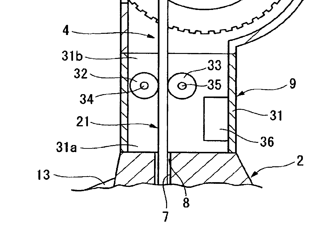
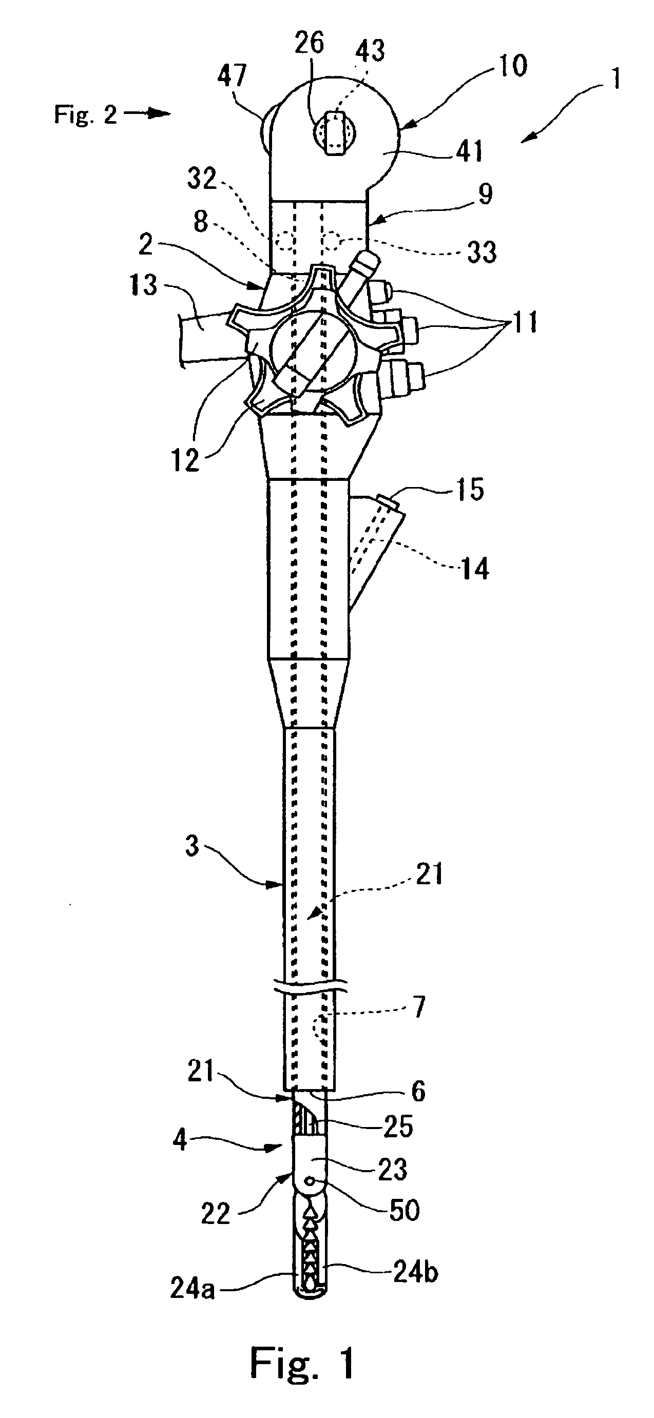
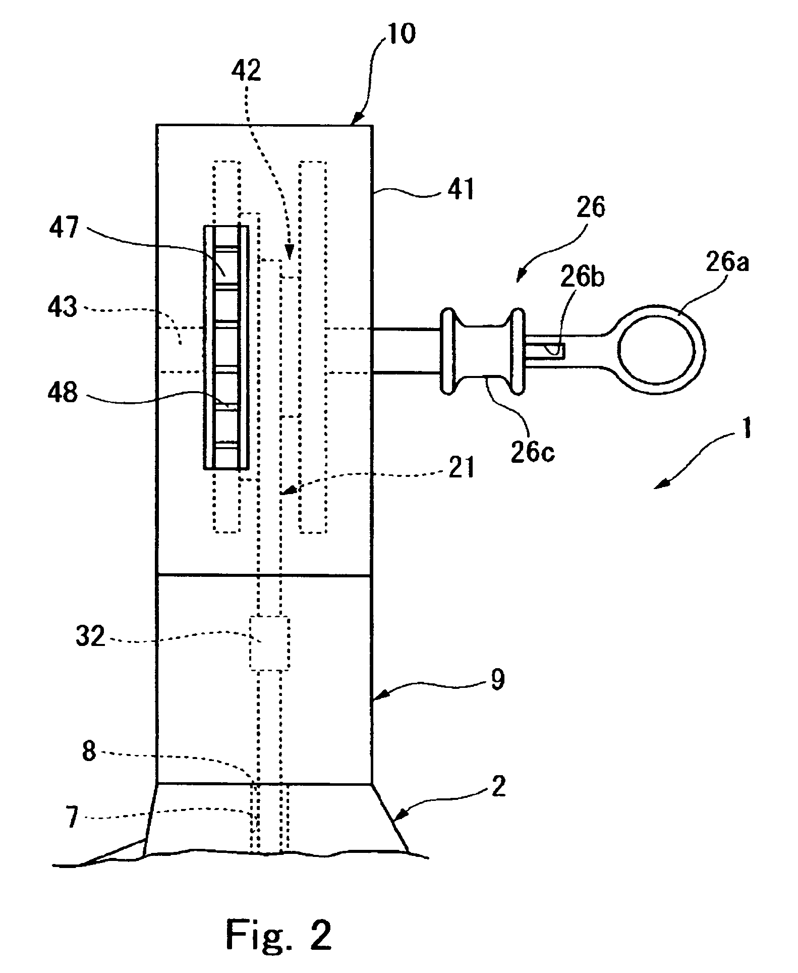
[0032] As shown in FIG. 1, an endoscope 1 has a final operating element 2 to be operated by an operator such as a practitioner, and a flexible insertion portion 3 to be inserted into a body cavity provided at the distal end of the final operating element 2. The insertion portion 3 is provided with an image-capturing device, an optical system (not shown) for illumination, and so on, and a distal opening 6 of a treatment tool channel 7 for receiving a treatment tool 4 to be inserted therethrough is provided at the distal end thereof. The treatment tool channel 7 penetrates the endoscope 1 from the distal end of the insertion portion 3 to the proximal end of the final operating element 2, and an insertion port 8 for inserting the treatment tool 4 is formed on the proximal side of the final operating element 2. A storage device 10 for the treatment tool 4 is mounted to the proximal end of the final operating ele...

third embodiment

[0074] Referring to FIG. 7, a third embodiment is described, in which components appearing in the above-described embodiments are represented by the same reference numerals and the description of which is omitted.

[0075] As shown in FIG. 7, this embodiment is characterized in that the dial member 80 serving as the fine-adjustment mechanism is provided separately from the roller 32.

[0076] An endoscope 81 includes a treatment tool insertion / withdrawal device 82 which is mounted to the proximal end of the final operating element 2. The storage device 63 is located nearer the proximal end of the treatment tool insertion / withdrawal device 82.

[0077] The treatment tool insertion / withdrawal device 82 includes a roller 84 that rotates in conjunction with the roller 32, and a dial member 80 that rotates in conjunction with the roller 84 in a cover 83. The dial member 80 is rotatably supported by a revolving shaft 85 on the cover 83, and is partly exposed outwardly via an opening 86 formed on...

second embodiment

[0079] Therefore, the same effects as in the second embodiment can be achieved. Since the ratio of the amount of rotation of the roller 32 with respect to the amount of rotation of the dial member 80 can be set to a predetermined value by the roller 84, the sensitivity of the fine-adjustment of the distal end position of the treatment tool 4 can be further fine-tuned.

[0080] The treatment tool insertion / withdrawal device 82 may be configured into a structure in which the roller 32 is rotated directly by the dial member 80 without the intermediary of the roller 84. It is also possible to provide a plurality of gears between the dial member 80 and the roller 32.

[0081] In the treatment tool insertion / withdrawal device 82, when the roller 32 is moved electrically, the dial member 80 is also driven. However, it is also possible to provide a transmission mechanism for mechanically connecting and disconnecting the roller 32 to / from the dial member 80 by a switch, not shown, between the rol...


PUM


Abstract

An endoscope is configured such that the position of the distal end of a treatment tool can be fine-adjusted when inserting and withdrawing the treatment tool into / from a treatment tool channel in the endoscope. For example, the treatment tool is inserted into the treatment tool channel of the endoscope and moved forward by a driving motor. When the distal end of the treatment tool projects from the treatment tool channel at the distal end of the endoscope, the forward movement is stopped, and the treatment tool is moved forward by manual operation. A method of manual operation includes the steps of rotating a dial and moving the treatment tool forward slowly. When in manual operation, the treatment tool is preferably released from any static torque of the motor.

Description

CROSS-REFERENCE TO RELATED APPLICATION [0001] This application is based upon and claims the benefit of priority from the prior Japanese Patent Application No. 2004-051365, filed Feb. 26, 2004. The entire contents of that application are incorporated herein by reference. BACKGROUND OF THE INVENTION [0002] 1. Field of the Invention [0003] The present invention relates to an endoscope (for medical and industrial use). More specifically, the present invention relates to a medical endoscope used for being inserted into a body of a human or an animal, or for industrial applications. [0004] 2. Description of the Related Art [0005] Performing inspection or observation by inserting into a cavity an endoscope insertion part (adapted for medical or industrial uses) is known. The endoscope has a flexible insertion portion, and an image-capturing means is provided at the distal end thereof, so that observation in the cavity is enabled. In many cases, the endoscope includes a treatment tool chann...

Claims


Application Information

Patent Timeline
Patent Type & Authority Applications(United States)
IPC IPC(8): A61B1/00A61B1/018A61B10/00A61B17/00A61B17/22A61B17/28A61B17/34A61M25/01
CPCA61B1/00133A61B1/018A61B17/29A61B2017/3445A61B2017/00469A61B2017/22075A61B2017/2905A61B2017/00398
Inventor IIZUKA, SHUHEINAGASE, TORUOKADA, TSUTOMUSUZUKI, KEITA
Owner OLYMPUS CORP
Why Eureka
Try Eureka