

Access and closure device and method
a technology of access and closure device and closure method, which is applied in the direction of surgical staples, catheters, applications, etc., can solve the problems of total occlusion of blood vessels, time-consuming method, and patient discomfort during procedur
- Summary
- Abstract
- Description
- Claims
- Application Information
AI Technical Summary
Benefits of technology
Problems solved by technology
Method used
Image

Examples
Embodiment Construction
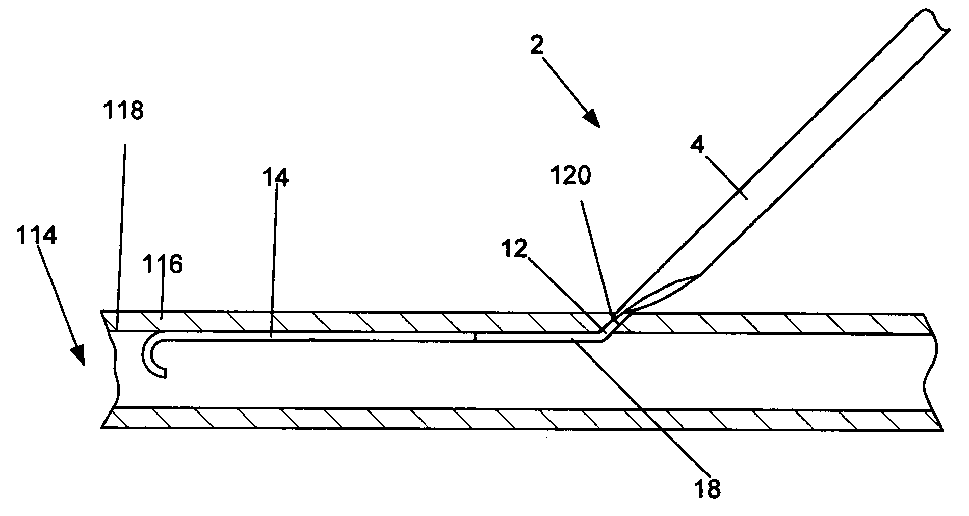
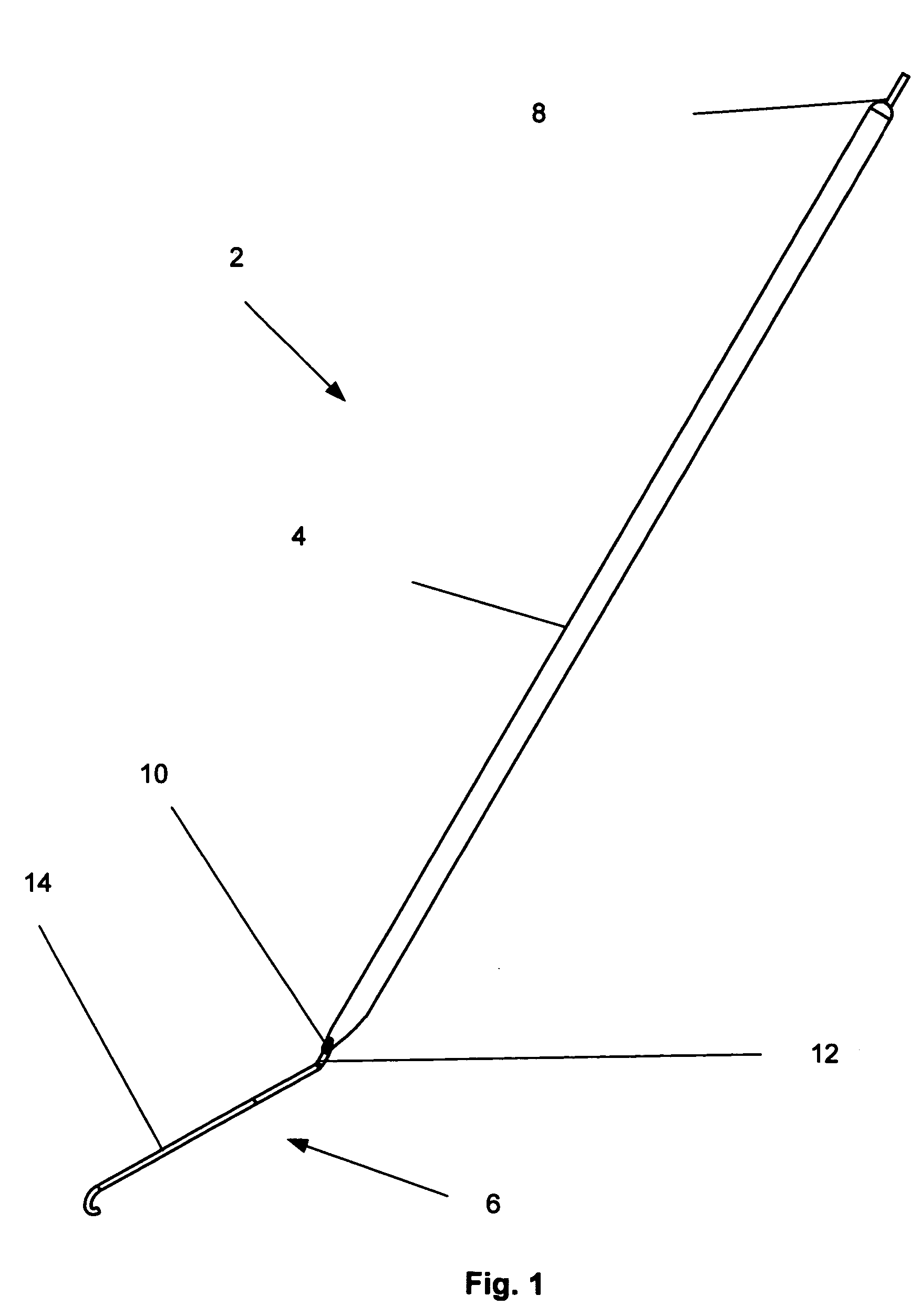
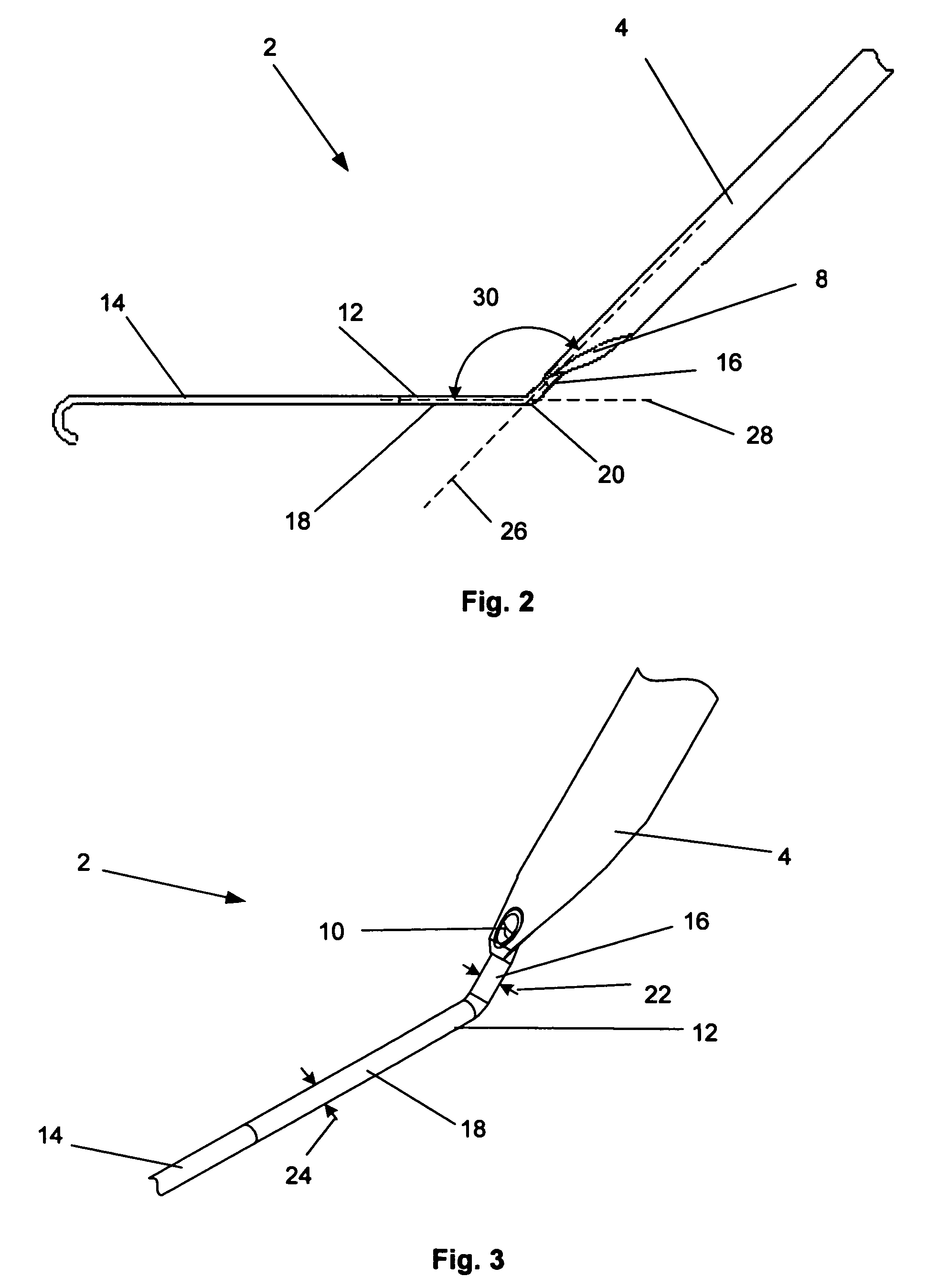
[0068]FIGS. 1 through 3 illustrate a device for accessing a biological lumen, such as an arteriotomy device 2. The arteriotomy device 2 can have a delivery guide 4. The delivery guide 4 can be slidably attached to an anchor 6. The anchor 6 can be rigid, flexible or combinations thereof. The anchor 6 can be resilient, deformable or combinations thereof. The anchor 6 can be retractable and extendable from the delivery guide 4. The delivery guide 4 can have an introducer lumen 8. The introducer lumen 8 can have an introducer lumen exit port 10. The introducer lumen exit port 10 can be on the surface of the delivery guide 4.
[0069] The anchor 6 can have an anchor angle section 12. The anchor 6 can have an anchor extension section 14, for example a guide eye sheath or an attachable guidewire. The anchor extension section 14 can extend from the anchor angle section 12. The anchor extension section 14 can be separate from and attached to, or integral with, the anchor angle section 12.
[007...
PUM
 Abstract
Description
Claims
Application Information