Stent monitoring assembly and method of use thereof

a technology of stents and assembly parts, applied in the field of vascular and nonvascular stents, can solve the problems of permanent neurological deficit, pain and shortness, and angina (pain and shortness), and achieve the effects of reducing the risk of strok

Inactive Publication Date: 2016-02-11
CANARAY MEDICAL INC
View PDF8 Cites 52 Cited by
  • Summary
  • Abstract
  • Description
  • Claims
  • Application Information

AI Technical Summary

Benefits of technology

[0025]As noted above, a wide variety of sensors can be utilized therein, including for example, fluid pressure sensors, contact sensors, position sensors, accelerometers, vibration sensors, pressure sensors, blood volume sensors, blood flow sensors, blood chemistry sensors, blood metabolic sensors, mechanical stress sensors, and temperature sensors. Within various embodiments the stent can be a vascular, gastrointestinal, pulmonary, sinus, or genitourinary stent, and

Problems solved by technology

Partial blockage of one or more coronary arteries is often due to the development and progression of arteriosclerotic plaque formation and results in angina (pain and shortness of breath with exercise), while complete blockage of a coronary artery is usually due to plaque rupture and thrombus formation and results in acute coronary syndrome (ACS) and/or myocardial infarction (heart attack).
In peripheral arterial disease, partial obstruction of blood vessels in the leg results in claudication (pain or “heaviness” with walking or exercise) and complete vascular obstruction leads to acute ischemia and gangrene; while in cerebral vascular disease narrowing of the blood vessels supplying the brain results in syncope (fainting), dizziness and transient numbness, weakness and speech abnormalities (to name a few symptoms) while complete obstruction results in cerebral vascular accidents (CVA or “strokes”) in the brain and permanent neurological deficits.
While there have recently been many advances in the construction, drug-loading, and delivery of stents, there are yet a number of deficiencies that have not yet been addressed.
Accurate placement, deployment, and full expansion of stents continues to be a challenge, particularly in the vasculature, where primarily indirect visualization techniques, such as angiography, are used for stent placement; angiography (radio-opaque dye running through the bloodstream) s

Method used


Image

  • Stent monitoring assembly and method of use thereof
  • Stent monitoring assembly and method of use thereof
  • Stent monitoring assembly and method of use thereof

Examples


embodiment 1

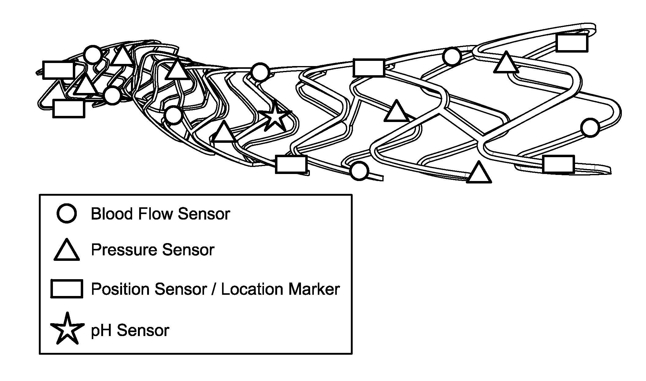
[0128]2) The assembly wherein the sensor is positioned on an outer wall of the stent.

[0129]3) The assembly according to embodiment 1 wherein the sensor is positioned on an inner wall of the stent.

[0130]4) The assembly according to embodiment 1 wherein the sensor is positioned within the stent.

[0131]5) The assembly according to embodiment 1 wherein the sensor is positioned on the luminal surface, adluminal surface, and / or implanted within a lumen.

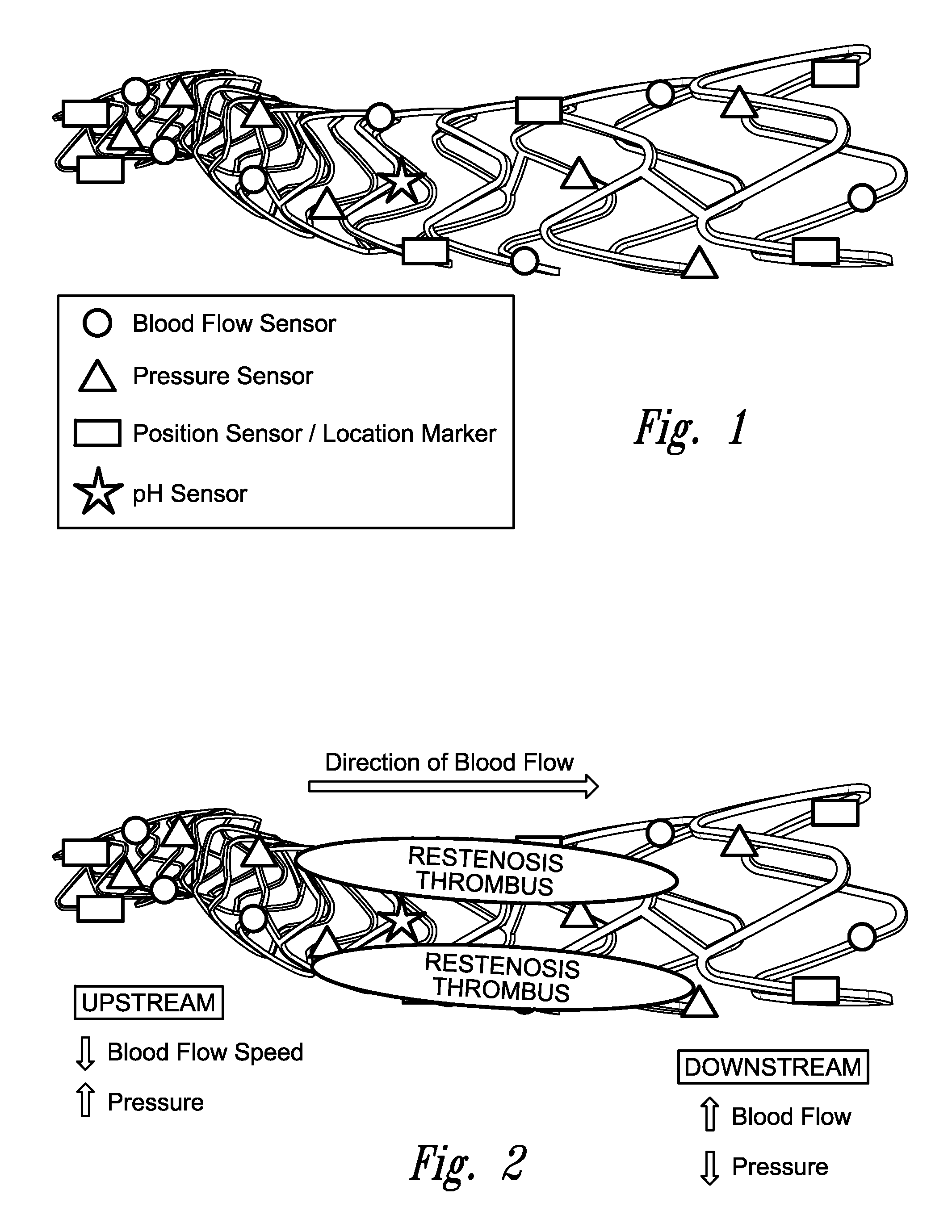
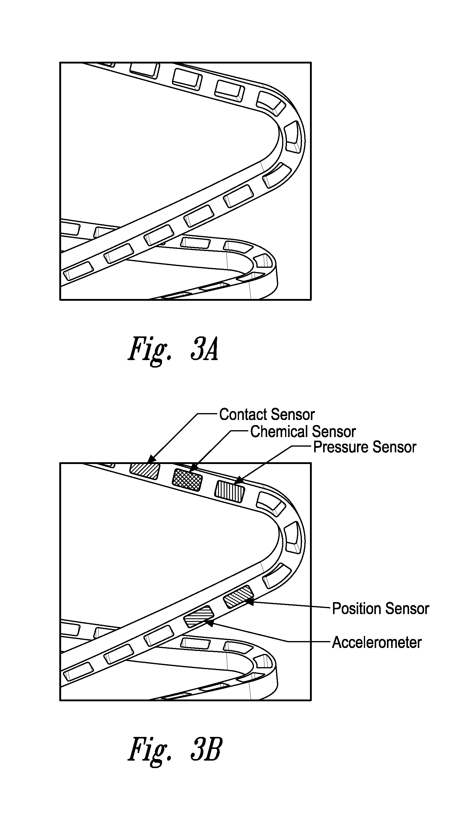
[0132]6) The assembly according to any one of embodiments 1 to 4 wherein the sensor is a fluid pressure sensor.

[0133]7) The assembly according to any one of embodiments 1 to 4 wherein the sensor is a contact sensor.

[0134]8) The assembly according to any one of embodiments 1 to 4 wherein the sensor is a position sensor.

[0135]9) The assembly according to any one of embodiments 1 to 4 wherein the sensor is a pulse pressure sensor.

[0136]10) The assembly according to any one of embodiments 1 to 4 wherein the sensor is a blood volume sensor

[0137]...

embodiment 15

[0142]16) The assembly wherein said vascular stent is a coronary stent, carotid stent, cerebral stent, vertebral stent, iliac stent, femoral stent, popliteal stent, or stent for the arteries of the lower extremities.

[0143]17) The assembly according to embodiment 15 wherein said gastrointestinal stent is an esophageal, duodenal, colonic, biliary or pancreatic stent.

[0144]18) The assembly according to embodiment 15 wherein said pulmonary stent is a stent that holds open the trachea, bronchi, bronchioles or alveoli.

[0145]19) The assembly according to embodiment 15 wherein said genitourinary stent is a ureteral stent, urethral stent, a prostatic stent, or a fallopian tube stent.

[0146]20) The assembly according to embodiment 15 wherein said head and neck stent is a sinus stent, a maxillary sinus stent, a frontal sinus stent, a lacrimal stent, a nasal stent, or a typanostomy tube.

[0147]21) The assembly according to any one of embodiments 1 to 20 wherein said stent is a biodegradable or p...

embodiment 32

[0159]32) The assembly wherein sensors are positioned on each of said two or more sections.

[0160]34) The assembly according to embodiment 32 wherein said sensors can be utilized to detect proper connection or assembly of a complete stent.

[0161]35) An assembly comprising a stent and a sensor, wherein said sensor measures the cardiac output of a subject.

[0162]36) An assembly comprising a stent and a sensor, wherein said sensor measures the stroke volume of a subject.

[0163]37) An assembly comprising a stent and a sensor, wherein said sensor measures the ejection fraction of a subject.

[0164]38) An assembly comprising a stent and a sensor, wherein said sensor measures the systolic blood pressure of a subject.

[0165]39) An assembly comprising a stent and a sensor, wherein said sensor measures the diastolic blood pressure of a subject.

[0166]40) An assembly comprising a stent and a sensor, wherein said sensor measures the mean arterial pressure of a subject.

[0167]41) An assembly comprising ...


PUM


Abstract

Assemblies are provided comprising a stent and a sensor positioned on and/or in the stent. Within certain aspects the sensors are wireless sensors, and include for example one or more fluid pressure sensors, contact sensors, position sensors, accelerometers, pulse pressure sensors, blood volume sensors, blood flow sensors, blood chemistry sensors, blood metabolic sensors, mechanical stress sensors and/or temperature sensors. Within certain aspects these stents may be utilized to assist in stent placement, monitor stent function, identify complications of stent treatment, monitor physiologic parameters and/or medically image a body passageway, e.g., a vascular lumen.

Description

CROSS-REFERENCE TO RELATED APPLICATION[0001]This application claims the benefit under 35 U.S.C. §119(e) of U.S. Provisional Patent Application No. 61 / 787,861 filed Mar. 15, 2013, which application is incorporated herein by reference in its entirety.FIELD OF THE INVENTION[0002]The present invention relates generally to the field of vascular and non-vascular stents and, more particularly, to stents for use in monitoring a variety of medical conditions, including, for example, development of restenosis, stent obstruction, and / or other diseasesBACKGROUNDDescription of the Related Art[0003]Stents are generally cylindrical, flexible, hollow, scaffold-like medical devices that can be inserted into body lumens to physically hold open structures and / or passageways (typically tubular organ structures such as blood vessels, the gastrointestinal tract, the urinary tract, the respiratory tract, or the male and female reproductive tracts) which have become blocked or partially obstructed thereby ...

Claims


Application Information

Patent Timeline
IPC IPC(8): A61B5/00A61B5/01A61B5/0205A61B5/0215A61B5/026A61B5/029A61B5/06A61B5/145A61F2/915
CPCA61B5/6862A61F2250/0096A61B5/065A61B5/026A61B5/029A61B5/145A61B5/01A61B5/0205A61B5/0024A61F2/915A61B5/0031A61B5/067A61B2562/0261A61F2250/0085A61B5/02158A61F2002/061A61F2002/067A61B5/1473A61B2560/0214A61B2562/0219A61B2560/0219
Inventor HUNTER, WILLIAM, L.
Owner CANARAY MEDICAL INC
Why Eureka
Try Eureka