
Methods, systems and devices related to road mounted indicators for providing visual indications to approaching traffic

a technology of visual indications and indicators, applied in the field of traffic safety and communication methods, systems and/or devices, can solve the problems of unobvious approach no functional path or detail to overcome real-world power and communication problems, etc., and achieves quick and convenient installation and removal, easy maintenance and replacement

Inactive Publication Date: 2005-12-08
SPOT DEVICES
View PDF99 Cites 172 Cited by
  • Summary
  • Abstract
  • Description
  • Claims
  • Application Information

AI Technical Summary

Benefits of technology

[0016] In another aspect, a traffic information system and / or visual indicator devices realize low power consumption, utilizing power modulation, signaling, and coding techniques to minimize the typical power consumption associated with wireless communications, while providing full functionality.
[0027] In another aspect, a traffic information system and / or visual indicator device provides reporting tools. A variety of reporting tools and / or options may be provided to administrators of from usage information to proactive notification of problems or communication errors. The content and format of said reporting provides a variety of usage information which can be used for a variety of needs, such as to show implementers how many times each traffic information system is used, allowing them to better gauge future traffic patterns and improve overall traffic safety.

Problems solved by technology

While prior approaches include hard-wired devices, they present no functional path or detail to overcoming real-world power and communication issues.
The approach used for these developments is unobvious, as it does not yet exist in any commercially available form relating to invention's market.

Method used


Image

  • Methods, systems and devices related to road mounted indicators for providing visual indications to approaching traffic
  • Methods, systems and devices related to road mounted indicators for providing visual indications to approaching traffic
  • Methods, systems and devices related to road mounted indicators for providing visual indications to approaching traffic

Examples


Embodiment Construction

[0071] In the following description, certain specific details are set forth in order to provide a thorough understanding of various disclosed embodiments. However, one skilled in the relevant art will recognize that embodiments may be practiced without one or more of these specific details, or with other methods, components, materials, etc. In other instances, well-known structures associated with transmitters, receivers, transceivers, charging circuits, power conditioning circuits, processors and / or controllers, and the like have not been shown or described in detail to avoid unnecessarily obscuring descriptions of the embodiments.

[0072] Unless the context requires otherwise, throughout the specification and claims which follow, the word “comprise” and variations thereof, such as, “comprises” and “comprising” are to be construed in an open, inclusive sense, that is as “including, but not limited to.”

[0073] Reference throughout this specification to “one embodiment” or “an embodime...


PUM


Abstract

A traffic informational system provides information to traffic moving along a road and may include a plurality of traffic information devices mountable to the road, each having an integral power producing source, at least a first set of illumination sources, and a wireless communications subsystem. The traffic informational system may further include at least a first external control device comprising at least one antenna and a transmitter communication wirelessly with the traffic information devices and / or with one another. The traffic information device may communicate with one another, and may include sensor for sensing ambient conditions. The system employs various approaches to reducing power consumption and improving communications, and is suitable for a wide range of applications, including use in remote environments.

Description

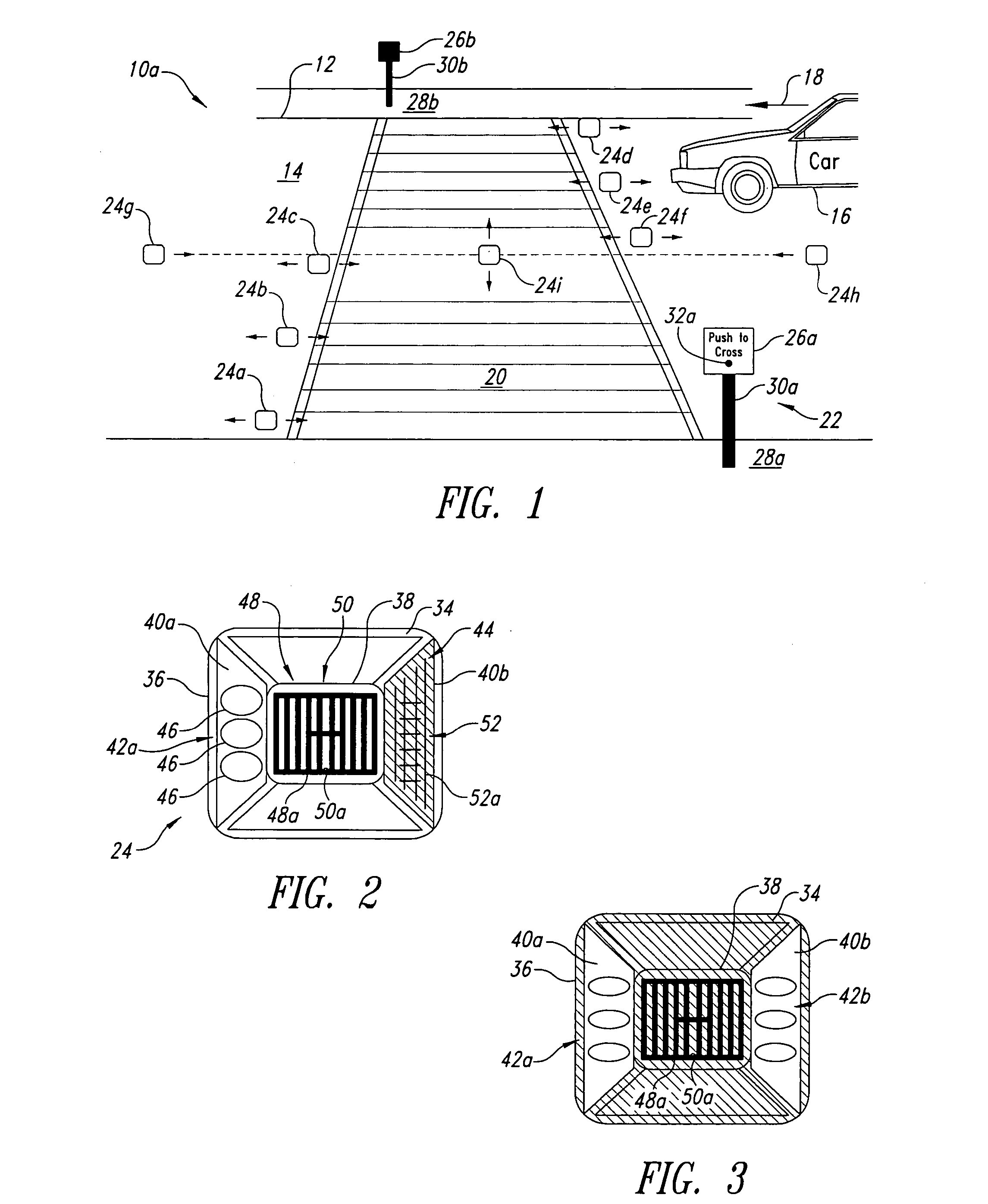
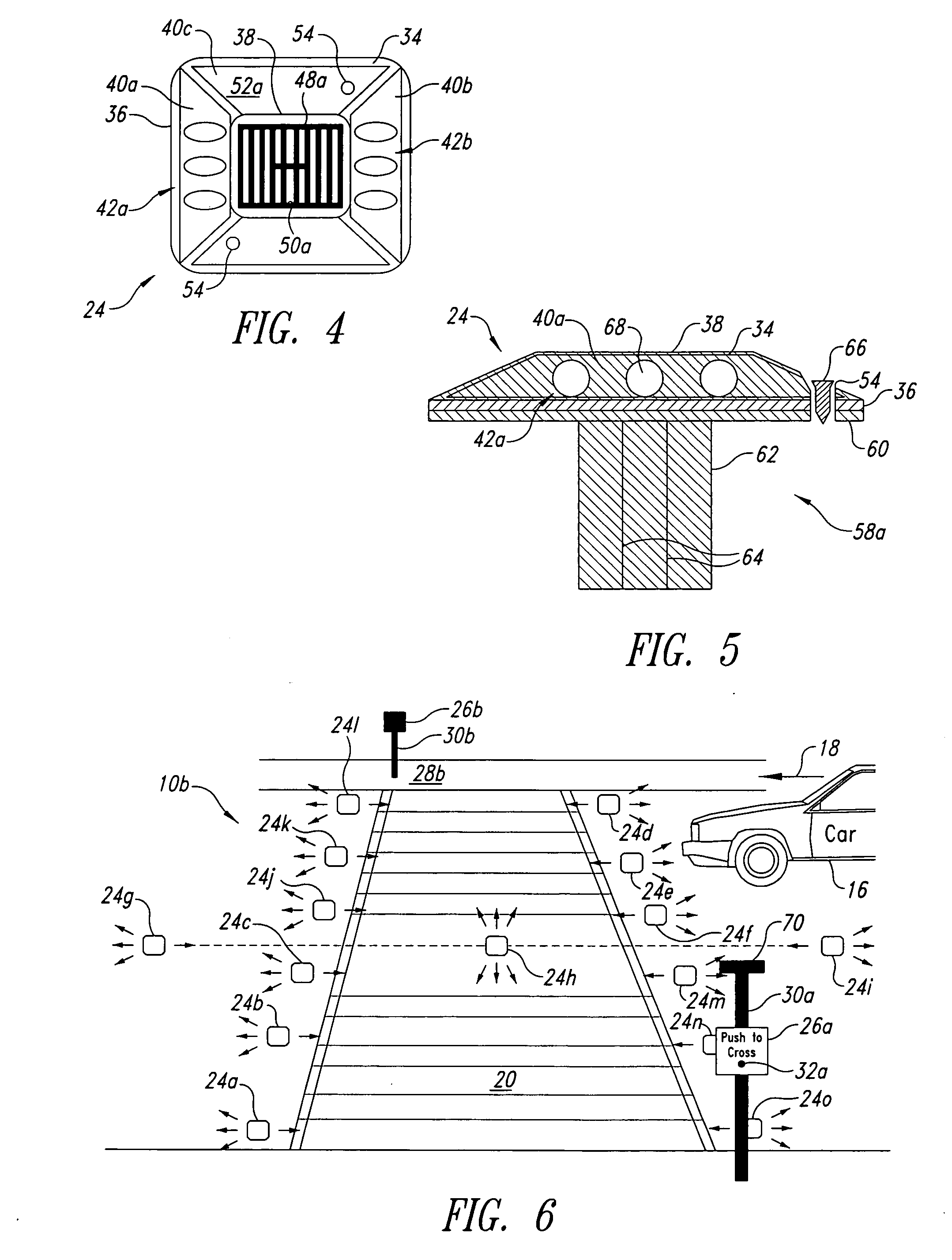
CROSS-REFERENCE TO RELATED APPLICATION [0001] This application claims the benefit under 35 U.S.C. § 119(e) of U.S. Provisional Patent Application No. 60 / 544,138, filed Feb. 13, 2004.BACKGROUND OF THE INVENTION [0002] 1. Field of the Invention [0003] This disclosure relates to traffic safety and communication methods, systems and / or devices, specifically for advanced warning and notification to vehicular and pedestrian traffic. [0004] 2. Description of the Related Art [0005] Prior approaches have employed a set of visual indicators mounted to a road to provide visual indications to approaching traffic. [0006] For example, U.S. Pat. No. 4,570,207 teaches locating the visual indicators in apertures or channels formed in a road, such that a top surface of each of the visual indicators is flush with the top surface of the road. The visual indicators are formed with an exterior that wears away, in a similar fashion to the top surface of the road, to maintain the top surface of the visual ...

Claims


Application Information

Patent Timeline
IPC IPC(8): E01F9/06G08G1/095G08G1/0967
CPCE01F9/065Y02B60/50G08G1/096783E01F9/559
Inventor PEDDIE, TIMM A.BIM-MERLE, DAVID P.BURNHAM, THOMAS A.SANTOS, DANIEL O.MILLER, LAWRENCE E.MEHTA, VINEETVAN NIEKERK, JOHANNES B.
Owner SPOT DEVICES
Learn More