Decoding with memory in RFID system

a technology of rfid system and decoding memory, which is applied in the direction of amplitude demodulation, pulse technique, instruments, etc., can solve the problems of reducing the signal available, affecting the operation of rfid system, and affecting the reception of received signals, so as to prolong the range of rfid system, improve the reception effect, and increase interference

Active Publication Date: 2005-12-08
IMPINJ
View PDF95 Cites 23 Cited by
  • Summary
  • Abstract
  • Description
  • Claims
  • Application Information

AI Technical Summary

Benefits of technology

[0009] The invention offers the advantage that poorer reception and more

Problems solved by technology

A challenge in the operation of RFID systems arises in decoding the received signal.
This is a problem both when tags are receiving from readers, and also when readers are receiving from tags.
Reception is hampered by factors of the environ

Method used


Image

  • Decoding with memory in RFID system
  • Decoding with memory in RFID system
  • Decoding with memory in RFID system

Examples


Embodiment Construction

proceeds with reference to the accompanying Drawings, in which:

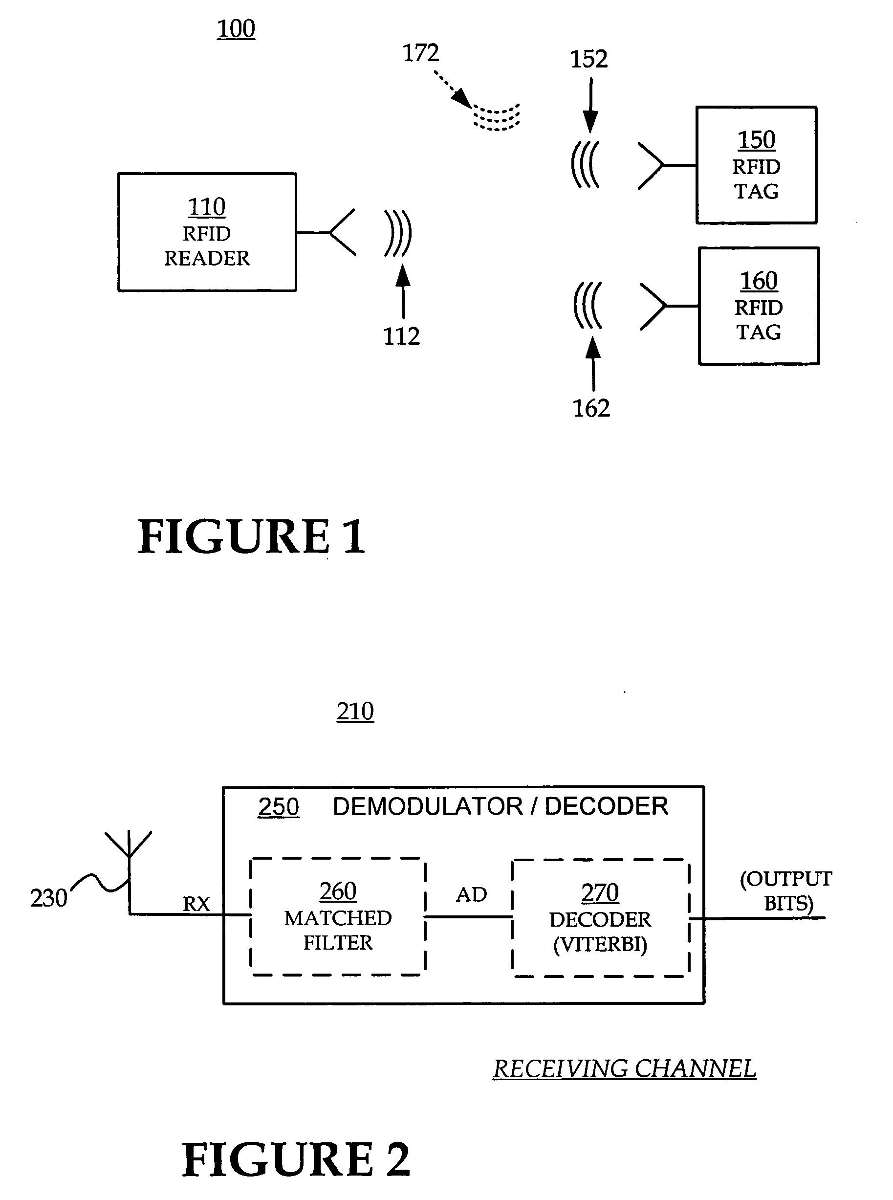
[0012]FIG. 1 is a diagram of an RFID system according to embodiments of the invention.

[0013]FIG. 2 is a block diagram of a receiving channel of an RFID reader and / or RFID tag according to embodiments of the invention.

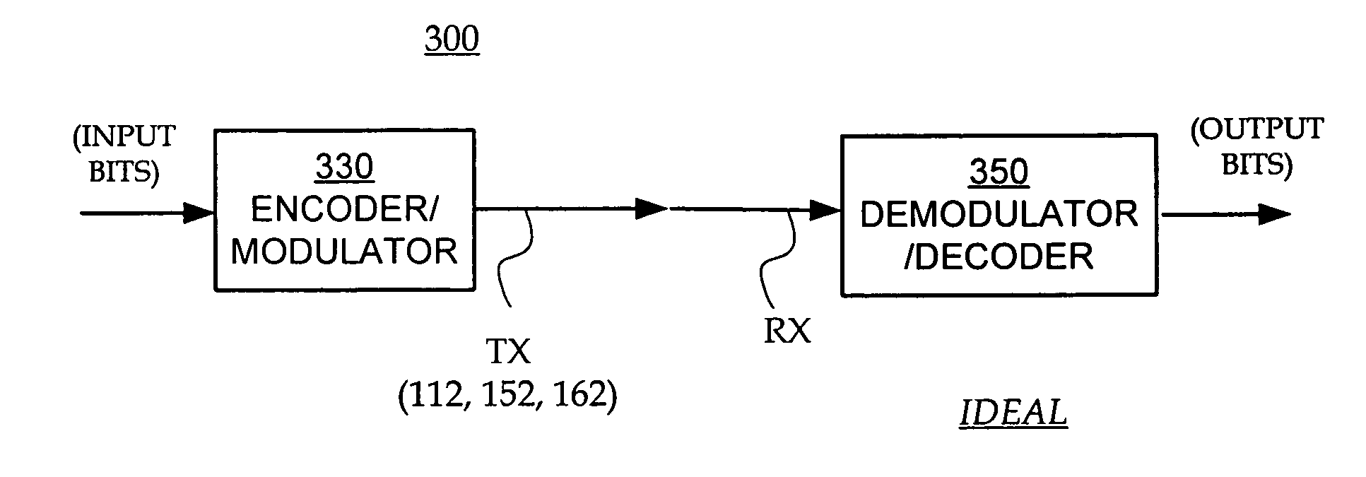
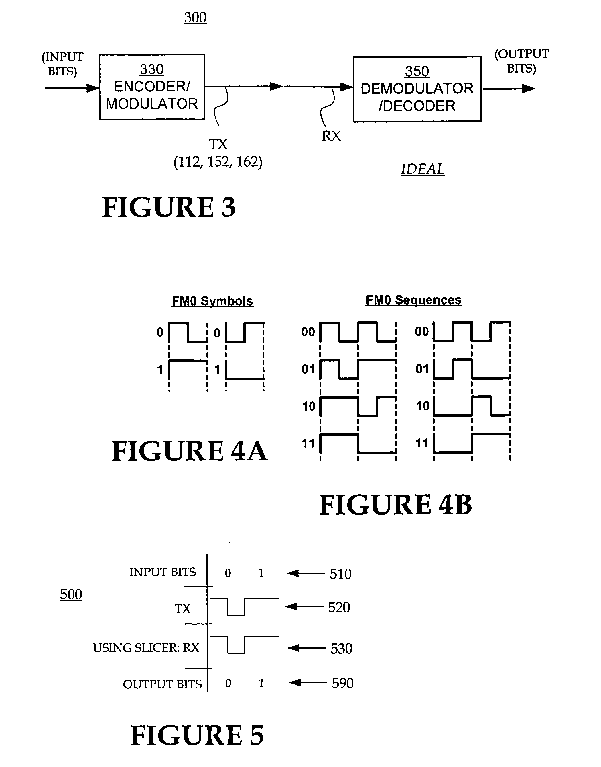
[0014]FIG. 3 is a diagram illustrating a model of idealized transmission and reception for the system of FIG. 1.

[0015]FIG. 4A illustrates the FM0 method for coding symbols in sequences for the transmission and reception of FIG. 3.

[0016]FIG. 4B illustrates examples to decide which of the waveforms of FIG. 4A are used in which case.

[0017]FIG. 5 is a table showing how input bits are transmitted and received to become output bits according to the model of FIG. 3, and using the sample method for coding of FIG. 4A and FIG. 4B.

[0018]FIG. 6 is a diagram illustrating a model of actual transmission and reception for the system of FIG. 1.

[0019]FIG. 7 is a table showing how input bits are transmitted and received...


PUM


Abstract

RFID readers, RFID tags, software, and methods decode a signal received in an RFID system. From received data, a decoder determines a number of possible test series for the output. In one embodiment, the decoder uses a memory of a previous sample to derive a subsequent sample in the test series, so as to ensure that all the test series are valid. A metric is then computed for how well each test series fits the received data. The metrics are compared to select for output the test series with the best fit. In a further embodiment, at least one of the metrics is further used to determine if a collision were present.

Description

FIELD OF THE INVENTION [0001] The present invention is related to the field of Radio Frequency IDentification (RFID) tags, and more specifically to RFID readers, tags, software and methods for decoding more accurately the received signal. BACKGROUND [0002] Radio Frequency IDentification (RFID) tags can be used in many ways for locating and identifying objects that they are attached to. RFID tags are particularly useful in product-related and service-related industries for tracking large numbers of objects are being processed, inventoried, or handled. In such cases, an RFID tag is usually attached to individual items, or to their packages. [0003] In principle, RFID techniques entail using a device called an RFID reader to interrogate one or more RFID tags. Interrogation is performed by the reader transmitting a Radio Frequency (RF) wave. A tag that senses the interrogating RF wave responds by transmitting back another RF wave, a process known as backscatter. Backscatter may take plac...

Claims


Application Information

Patent Timeline
IPC IPC(8): G06K7/00H03M7/00
CPCG06K7/0008
Inventor ESTERBERG, AANAND
Owner IMPINJ
Why Eureka
Try Eureka