Sensor for capacitive touch pad pointing device

a capacitive touch pad and pointing device technology, applied in the direction of instruments, computing, electric digital data processing, etc., can solve the problem of corresponding cost increas

Inactive Publication Date: 2005-12-08
SEMTECH CORP
View PDF32 Cites 142 Cited by
  • Summary
  • Abstract
  • Description
  • Claims
  • Application Information

AI Technical Summary

Benefits of technology

[0010] The current invention teaches the topology and shape of sensing electrodes on the Capacitive Touch Pad Sensor that allow sensing of small targets. One specific implementation shown in FIGS. 1 through 4 provides for a 5× improvement for the size of the mi

Problems solved by technology

However, this approach necessitates a corresponding increase in the number of signal lines on the sensing and controlling circ

Method used


Image

  • Sensor for capacitive touch pad pointing device
  • Sensor for capacitive touch pad pointing device
  • Sensor for capacitive touch pad pointing device

Examples


Embodiment Construction

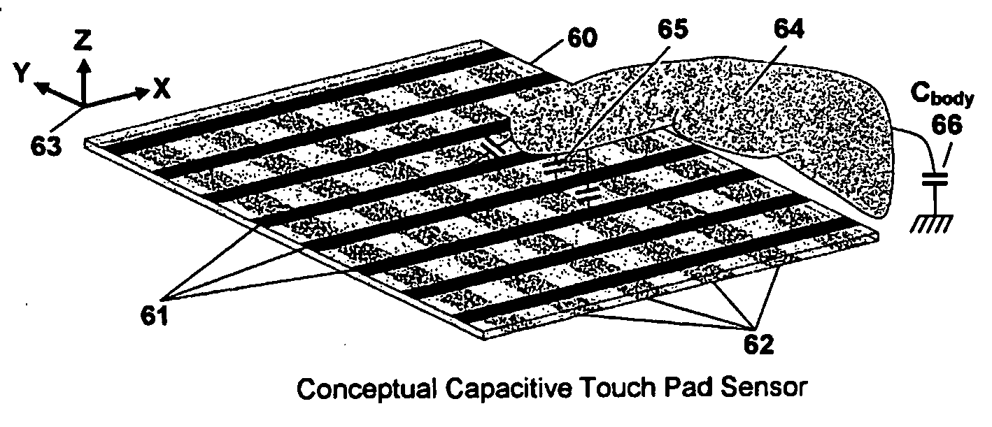
[0018] It is desirable for Rows to occupy the whole top area of the Capacitive Touch Pad, with only small isolation gaps between individual Rows, when the measurements of the Y-axis are made; and for the Columns to occupy the whole top area of the Capacitive Touch Pad when the measurements of the X-axis are made. However, it is not practical, since the top area must be shared. The current invention allows for the Rows and Columns to have minimal gaps of coverage as compared to the Prior Art implementations.

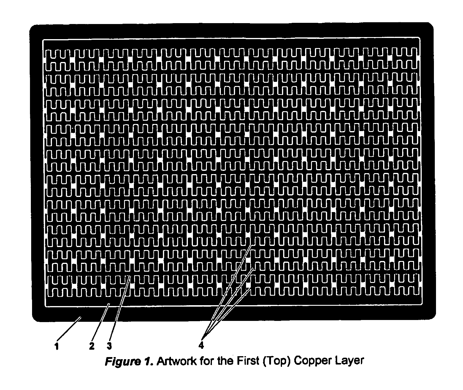
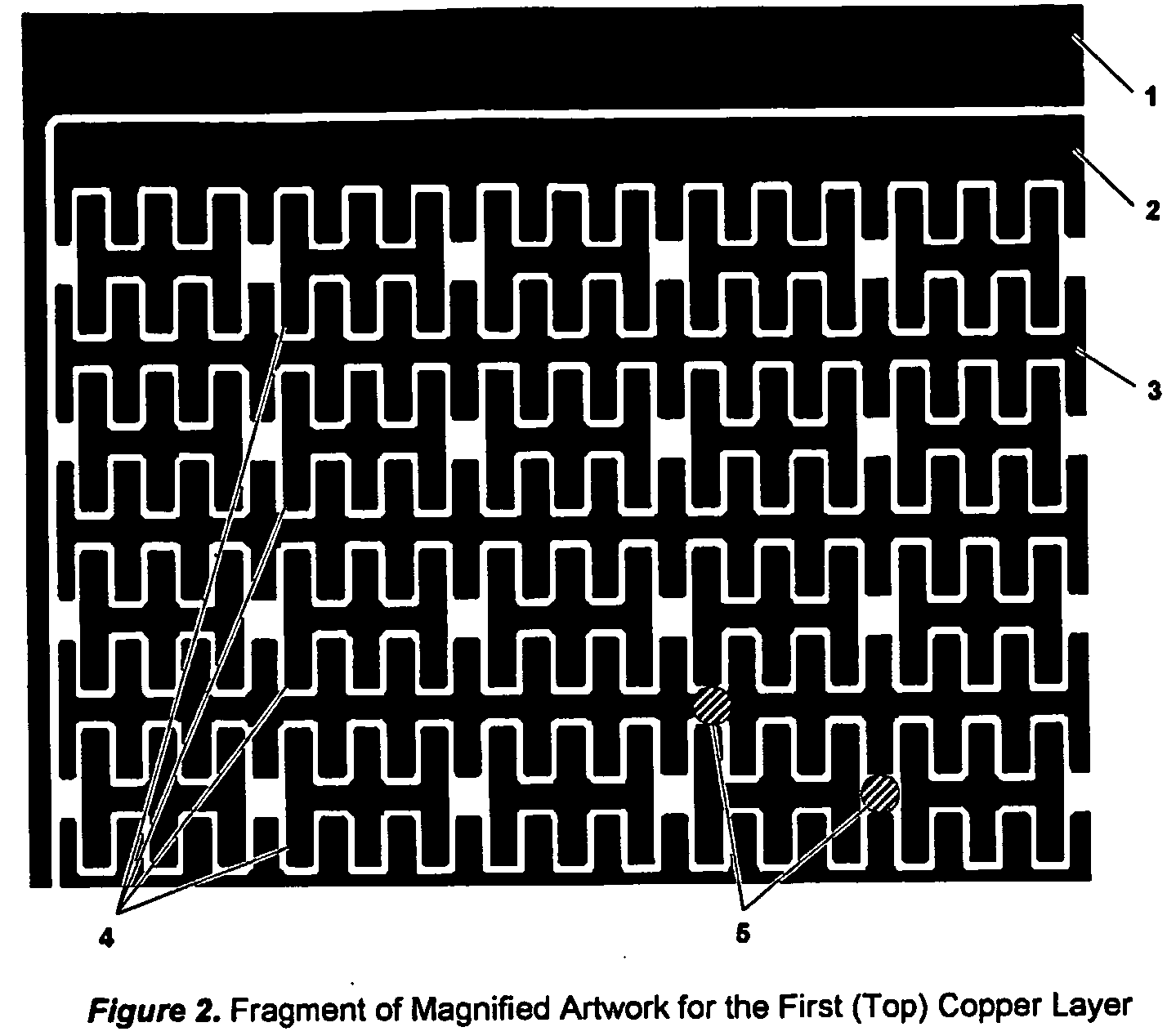
[0019] Referring to FIG. 1 and FIG. 2, the Rows 3 are created by utilizing a “double-comb” pattern. It is desirable to have as many “fingers” as possible per unit of length, however the limitations of the manufacturing process impose a bound upon the minimum feature size, both for the copper conductors and for the spaces between them. The Sensor illustrated in FIGS. 1 through 4 can be produced with a standard low-cost PCB process often called “8 / 8”, meaning that both the minimum ...


PUM


Abstract

The topology and the shape of sensing electrodes (4, 31) on the Capacity Touch Pad Sensor that allow sensing of small targets are disclosed. Sensor construction utilizes common PCB manufacture technique.

Description

[0001] This application claims priority from U.S. appl. No. 60 / 320,276 filed Jun. 13, 2003, which application is hereby incorporated herein by reference for all purposes.BACKGROUND ART [0002] Modern computing devices typically utilize some form of pointing device for interactions of the user(s) with the Operating System (OS) or Graphical User Interface (GUI). The Capacitive Touch Pad (CTP) is well established as the pointing device of choice for Laptop and Notebook portable computers, and other devices. [0003] A Conceptual Capacitive Touch Pad 60 is demonstrated in FIG. 6. A non-conductive cover that provides galvanic isolation between the user's hand and the Sensor is omitted for clarity here and in FIGS. 1 through 4. [0004] Two groups of electrodes 61 and 62 are utilized. Group 61, with electrodes parallel to the X-axis, is used for determination of the Y coordinate (according to the system of coordinates depicted as 63). Group of electrodes 62, with electrodes parallel to the Y-a...

Claims


Application Information

Patent Timeline
IPC IPC(8): G06F3/044G09G5/00H05K
CPCG06F3/044G06F3/0445G06F3/0446
Inventor MARTEN, VICTOR
Owner SEMTECH CORP
Why Eureka
Try Eureka