
Dual source tracking servo systems and associated methods

a servo system and dual source technology, applied in the field of magnetic tape storage devices and systems, can solve the problems of static shift, unstable ltm, and increased risk of errors in the tape, and achieve the effects of avoiding static shift, avoiding static shift, and avoiding static shi

Inactive Publication Date: 2005-12-08
QUANTUM CORP
View PDF99 Cites 16 Cited by
  • Summary
  • Abstract
  • Description
  • Claims
  • Application Information

AI Technical Summary

Benefits of technology

The present invention provides servo systems and methods for determining the position of a transducer head relative to a magnetic storage tape using existing data structures on the tape and a fixed reference associated with the tape. This allows for precise positioning of the transducer head for accurate data reading and writing. The invention includes a dual source tracking servo system and a method for weighting the position of the transducer head based on the previously written data track and the position of the fixed reference. The technical effects of the invention include improved accuracy and efficiency in positioning the transducer head for data reading and writing.

Problems solved by technology

The tape therefore becomes more susceptible to errors caused from the tape shifting up or down (called lateral tape motion or “LTM”) in a direction perpendicular to the tape travel path as the tape passes by the magnetic head.
Some may cause abrupt momentary jumps while others may cause a static shift.
Generally, LTM is unpredictable and unrepeatable.
In multi-head, multi-channel magnetic tape storage systems, random lateral tape motion is generally a limiting factor in achieving higher track densities and thus higher user data capacity per tape.
Miss-registration between the head and the data track can cause data errors during readback and data loss on adjacent tracks during writing.

Method used


Image

  • Dual source tracking servo systems and associated methods
  • Dual source tracking servo systems and associated methods
  • Dual source tracking servo systems and associated methods

Examples


Embodiment Construction

[0019] Various exemplary methods and systems for providing calibration and / or position information to a servo system are provided. The following description is presented to enable a person of ordinary skill in the art to make and use the invention. Descriptions of specific materials, techniques, and applications are provided only as examples. Various modifications to the examples described herein will be readily apparent to those skilled in the art, and the general principles defined herein may be applied to other examples and applications without departing from the spirit and scope of the inventions.

[0020] Accurately positioning a transducer head with respect to a storage tape and data tracks within a tape drive during writing and reading processes is one of the main challenges in the area of magnetic storage tape systems. Generally, a closed loop servo system, deployed by the tape drive electromechanical system, utilizes an estimate of the head's position relative to the storage ...


PUM

PropertyMeasurementUnit
magneticaaaaaaaaaa
linear velocityaaaaaaaaaa
widthaaaaaaaaaa

Abstract

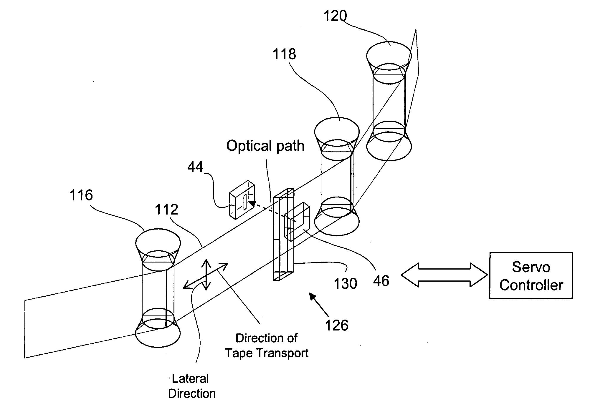
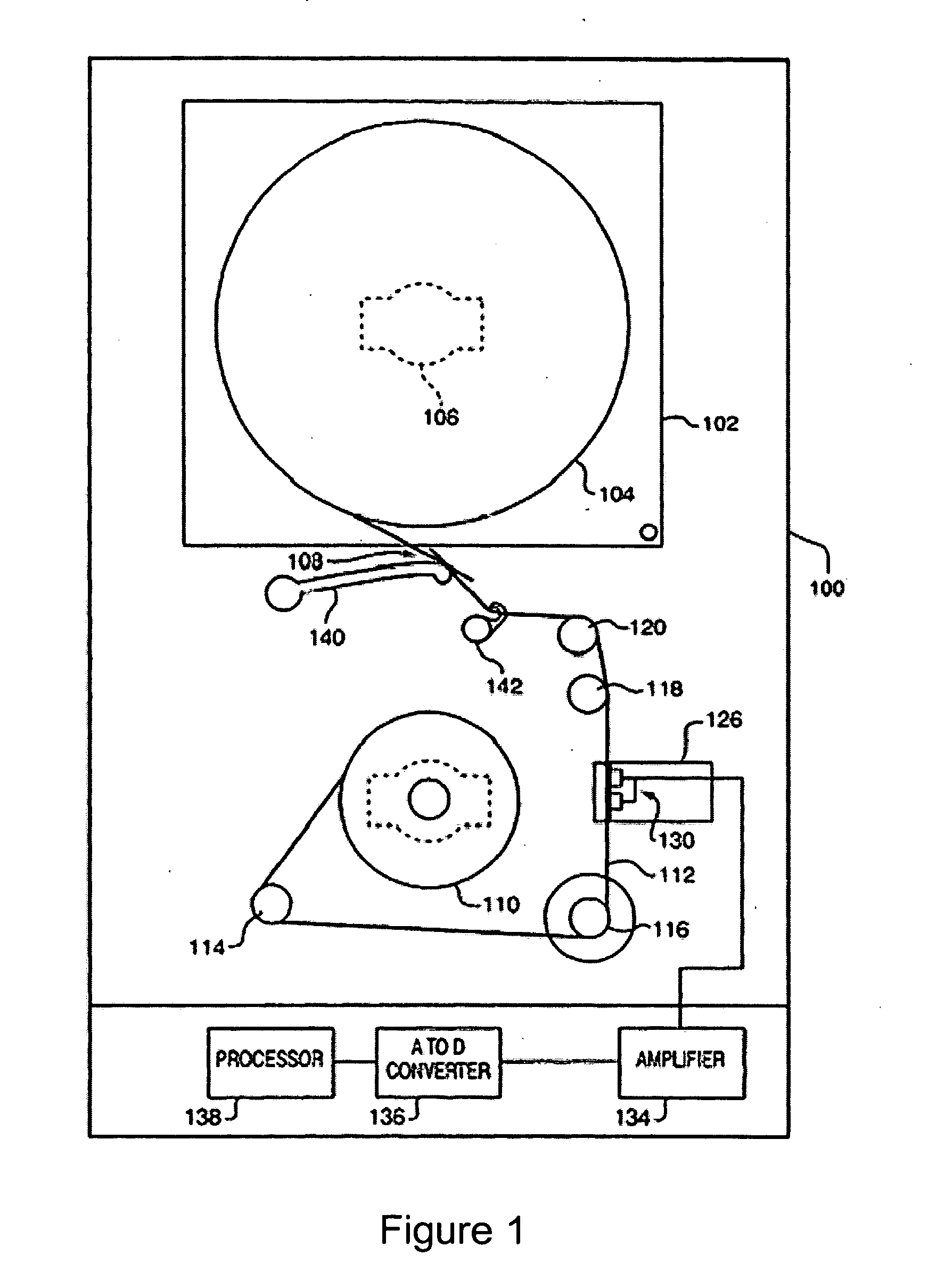
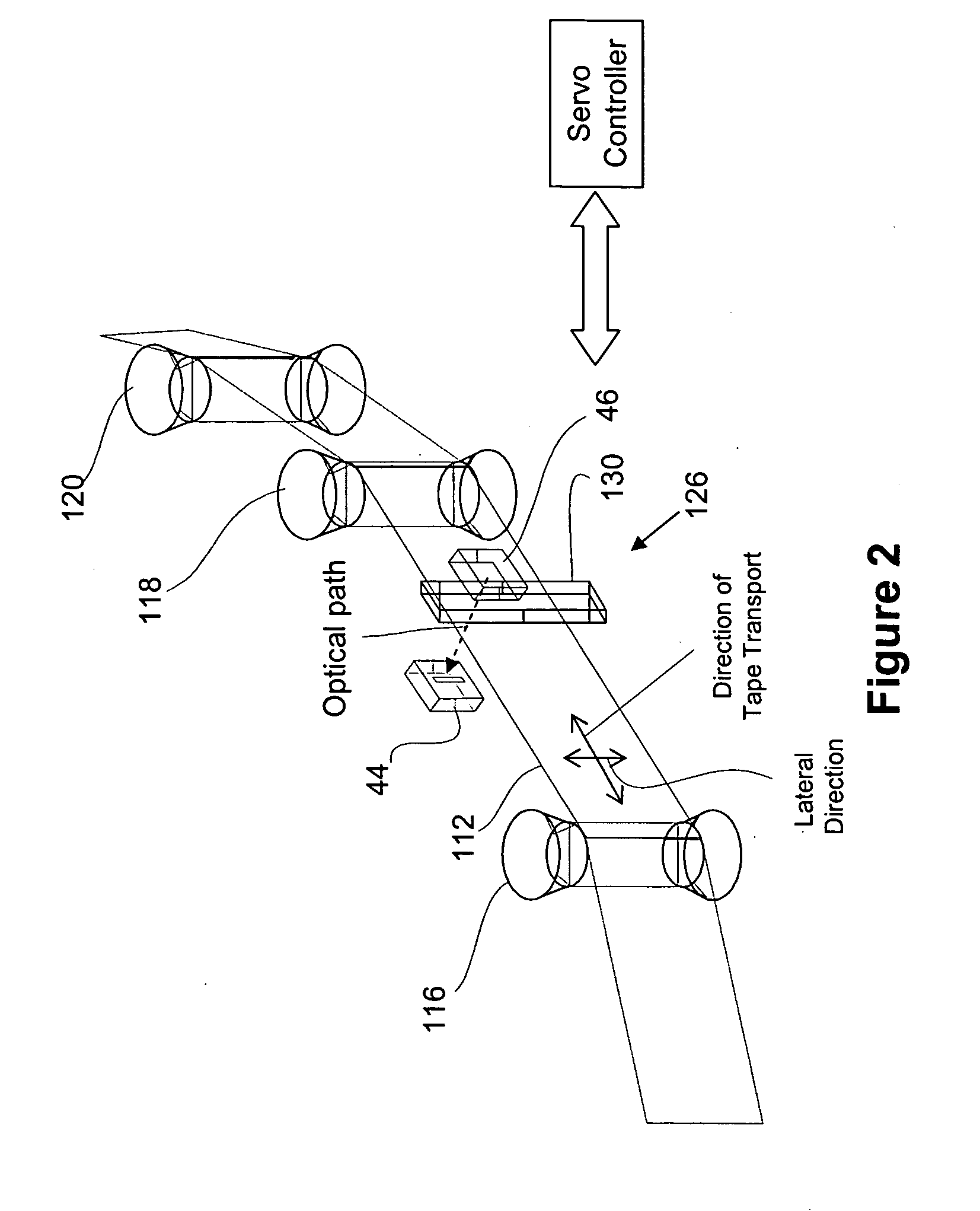
In one example, a dual source tracking servo system includes a head assembly having a data transducer, a primary position detector for sensing the position of a magnetically stored data track, and a secondary position detector for sensing the position of a fixed reference associated with a magnetic storage medium. A controller is configured for adjusting the position of the head assembly in response to a weighted average of the sensed position of the magnetically stored data track and the fixed reference, wherein the position of the magnetically stored data track is weighted more than the position of the fixed reference. The primary position detector may include one or more dedicated servo read elements associated with the head assembly and the secondary position detector may include a magnetic or optical sensor. The fixed reference may include a tape edge or servo track.

Description

BACKGROUND [0001] 1. Field of the Invention [0002] The invention and its various aspects relate generally to magnetic tape storage devices and systems, and more particularly to methods and systems for head positioning servo systems. [0003] 2. Description of the Related Art [0004] Digital tape-recording remains a viable solution for storage of large amounts of data. Conventionally, at least two approaches are employed for recording digital information onto magnetic recording tape. One approach calls for moving a magnetic tape past a rotating head structure that reads and writes user information from discontinuous transverse tracks. Interactive servo systems are typically employed to synchronize rotation of the head structure with travel of the tape. Another approach is to draw the tape across a non-rotating head at a considerable linear velocity. This approach is sometimes referred to as linear “streaming” tape recording and playback. [0005] Increased data storage capacity, and retri...

Claims


Application Information

Patent Timeline
Patent Type & Authority Applications(United States)
IPC IPC(8): G11B5/584
CPCG11B5/584
Inventor ZWEIGHAFT, JAMES
Owner QUANTUM CORP
Learn More