
Method and apparatus for transmitting/receiving transmission status information and buffer state information in a mobile communication system that supports uplink packet service

a mobile communication system and packet service technology, applied in multiplex communication, wireless commuication services, high-level techniques, etc., can solve the problems of unnecessary power consumption and increased uplink interference level, and achieve and efficient transmission power status information

Active Publication Date: 2005-12-08
NOKIA SOLUTIONS & NETWORKS OY
View PDF4 Cites 16 Cited by
  • Summary
  • Abstract
  • Description
  • Claims
  • Application Information

AI Technical Summary

Benefits of technology

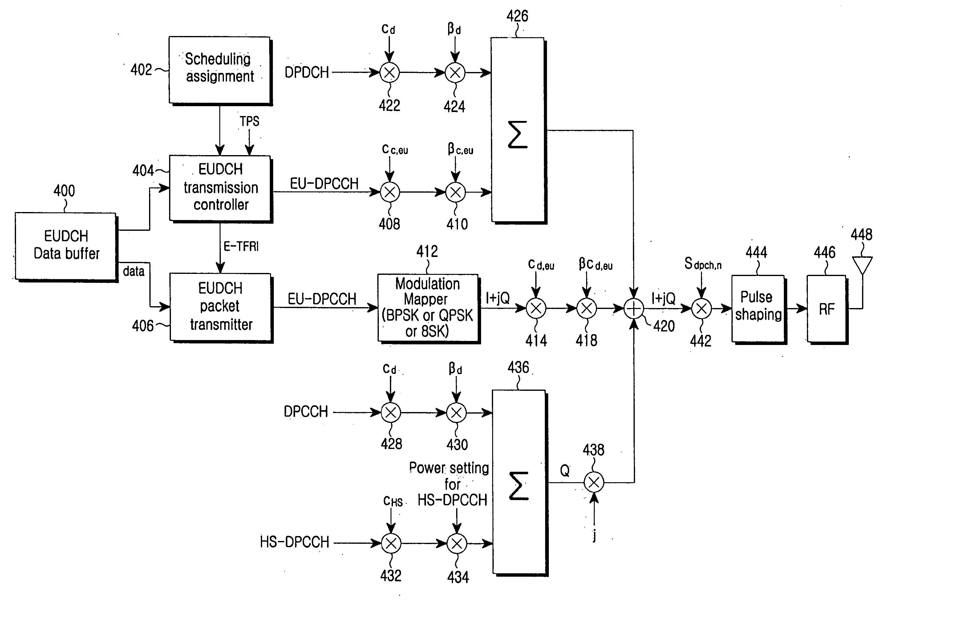
[0024] Accordingly, the present invention has been designed to solve the above and other problems occurring in the prior art, and an object of the present invention is to provide a method and apparatus for efficiently transmitting / receiving buffer state and transmission power status information in a mobile communication system that supports an uplink packet service.
[0025] Another object of the present invention is to provide a method and apparatus that can secure a stable transmission / reception between a user equipment (UE) and a Node B in transmitting buffer state and transmission power status information in a mobile communication system that supports an uplink packet service.
[0026] Still another object of the present invention is to provide a method and apparatus that can reduce a signaling overhead in transmitting buffer state and transmission power status information in a mobile communication system that supports an uplink packet service.

Problems solved by technology

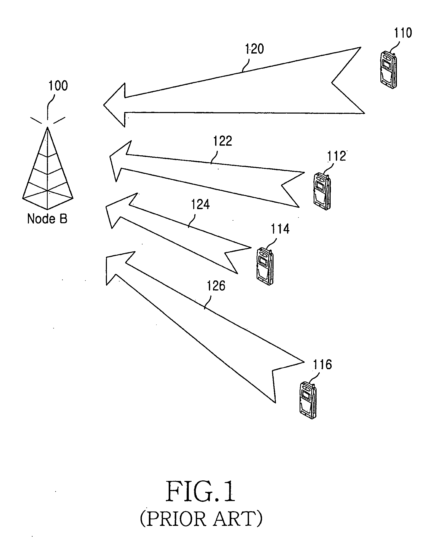
Accordingly, even in the case in which the packet data to be transmitted does not exist in the EUDCH packet data buffer, the UE continuously reports the TPS, and this causes an uplink interference level to be increased.
Additionally, due to the demodulation / decoding of the TPS that is periodically transmitted from the transmitter of the UE and the receiver of the Node B, unnecessary power is consumed.

Method used


Image

  • Method and apparatus for transmitting/receiving transmission status information and buffer state information in a mobile communication system that supports uplink packet service
  • Method and apparatus for transmitting/receiving transmission status information and buffer state information in a mobile communication system that supports uplink packet service
  • Method and apparatus for transmitting/receiving transmission status information and buffer state information in a mobile communication system that supports uplink packet service

Examples


first embodiment

[0084] In the first embodiment of the present invention, a scheme for simultaneous transmission of the BO and TPS using the MAC-e signaling and a scheme for end report by the UE will be explained in detail. Specifically, the report of the transmission power state starts through the scheme for simultaneous transmission of the BO and TPS using the MAC-e signaling, and then the report of the transmission power state ends through the scheme for end report by the UE.

[0085]FIG. 5 is a diagram illustrating the transmission timing of the BO and TPS according to the first embodiment of the present invention.

[0086] Referring to FIG. 5, if data to be transmitted does not exist in the EUDCH packet data buffer, the UE does not start the report of the BO and the TPS (reference numeral 500). Accordingly, the Node B does not transmit the scheduling assignment information to the UE (reference numeral 502).

[0087] At the time point 504, the UE starts the transmission of the BO and the TPS if data t...

second embodiment

[0122] Hereinafter, in the second embodiment of the present invention, a scheme for implicit start report using the BO and implicit end report using the BO will be explained in detail.

[0123]FIG. 8 is a view illustrating the transmission timing of the BO and the TPS according to the second embodiment of the present invention.

[0124] Referring to FIG. 8, if data to be transmitted does not exist in the EUDCH packet data buffer, the UE does not start the report of the BO. Accordingly, the Node B does not transmit the scheduling assignment information to the UE.

[0125] At the time point 700, the UE starts the transmission of the BO if data that exceeds the specified threshold value exists in the EUDCH packet data buffer. Reference numeral 702 denotes a start time point of the BO transmission. The BO is reported to the Node B through the MAC-e control signaling. This means that the UE reports the start of the TPS report to the Node B. That is, it is called the ‘start of the transmission ...

third embodiment

[0149] Hereinafter, in the third embodiment of the present invention, a scheme for implicit start report using the BO and end report by the Node B will be explained in detail.

[0150]FIG. 11 is a view illustrating the transmission timing of the BO and the TPS according to the third embodiment of the present invention.

[0151] Referring to FIG. 11, if data to be transmitted does not exist in the EUDCH packet data buffer, the UE does not start the report of the BO. Accordingly, the Node B does not transmit the scheduling assignment information to the UE.

[0152] The UE starts the transmission of the BO if data that exceeds the specified threshold value exists in the EUDCH packet data buffer. The BO is reported to the Node B through the MAC-e control signaling. This means that the UE reports the start of the TPS report to the Node B. That is, it is called the ‘start of the transmission power status report’. This is because the Node B can confirm that the data to be transmitted from the UE...


PUM


Abstract

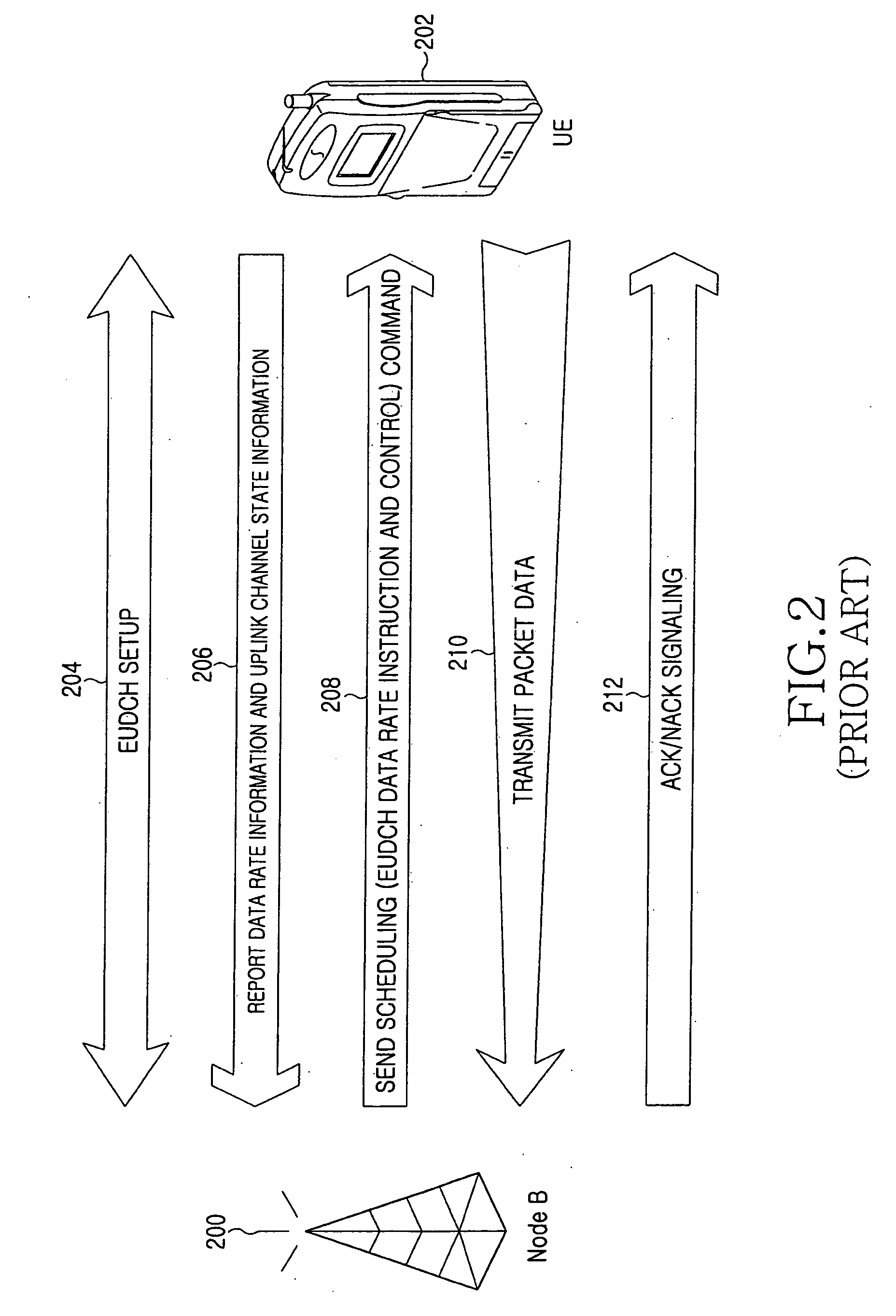
Disclosed is a method and apparatus for efficiently transmitting / receiving transmission power status information (TPS) and buffer state information (BO) of a user equipment (UE). Under the assumption that an enhanced uplink dedicated transport channel (EUDCH) is used for an uplink data transmission in an asynchronous code division multiple access (CDMA) system, a scheduler of a Node B performs a scheduling operation such as transmission timing of EUDCH packet data, data rate assignment, and the like. The scheduler receives the EUDCH packet data BO, TPS, and the like, and efficiently performs processes of start / continuation / end of the TPS transmission.

Description

PRIORITY [0001] This application claims the benefit under 35 U.S.C. 119(a) of applications entitled “Method and Apparatus for Transmitting / Receiving Transmission Status Information and Buffer State Information in Mobile Communication System That Supports Uplink Packet Service” filed in the Korean Industrial Property Office on May 6, 2004 and assigned Serial No. 2004-32015, Jun. 14, 2004 and assigned Serial No. 2004-43762, Oct. 14, 2004 and assigned Serial No. 2004-82072, and Oct. 15, 2004 and assigned Serial No. 2004-82615, respectively, the entire contents of which are hereby incorporated by reference. BACKGROUND OF THE INVENTION [0002] 1. Field of the Invention [0003] The present invention relates generally to a mobile communication system that supports an uplink packet transmission service. More particularly, the present invention relates to a method and apparatus for efficiently transmitting / receiving transmission power information and buffer state information of a user equipmen...

Claims


Application Information

Patent Timeline
Patent Type & Authority Applications(United States)
IPC IPC(8): H04B1/707H04B7/26H04J3/24H04J13/00H04W8/24H04W28/00H04W28/12H04W28/14H04W28/22H04W72/12
CPCH04L1/0025H04L1/0026H04L1/1812H04L5/0053Y02D70/00H04W28/22H04W72/1284Y02D70/1242Y02D70/1244H04W28/14Y02D30/70H04W72/21
Inventor CHO, JOON-YOUNGLEE, JU-HOKIM, YOUNG-BUMHEO, YOUN-HYOUNGKWAK, YONG-JUNVAN LIESHOUT, GERT JANHWANG, SUNG-OH
Owner NOKIA SOLUTIONS & NETWORKS OY
Learn More