
Printing apparatus, POS system and printing apparatus control method

a printing apparatus and control method technology, applied in the field of printing apparatus, can solve the problems of complicated and expensive process of modifying the pos application itsel

Inactive Publication Date: 2005-12-08
SEIKO EPSON CORP
View PDF5 Cites 57 Cited by
  • Summary
  • Abstract
  • Description
  • Claims
  • Application Information

AI Technical Summary

Benefits of technology

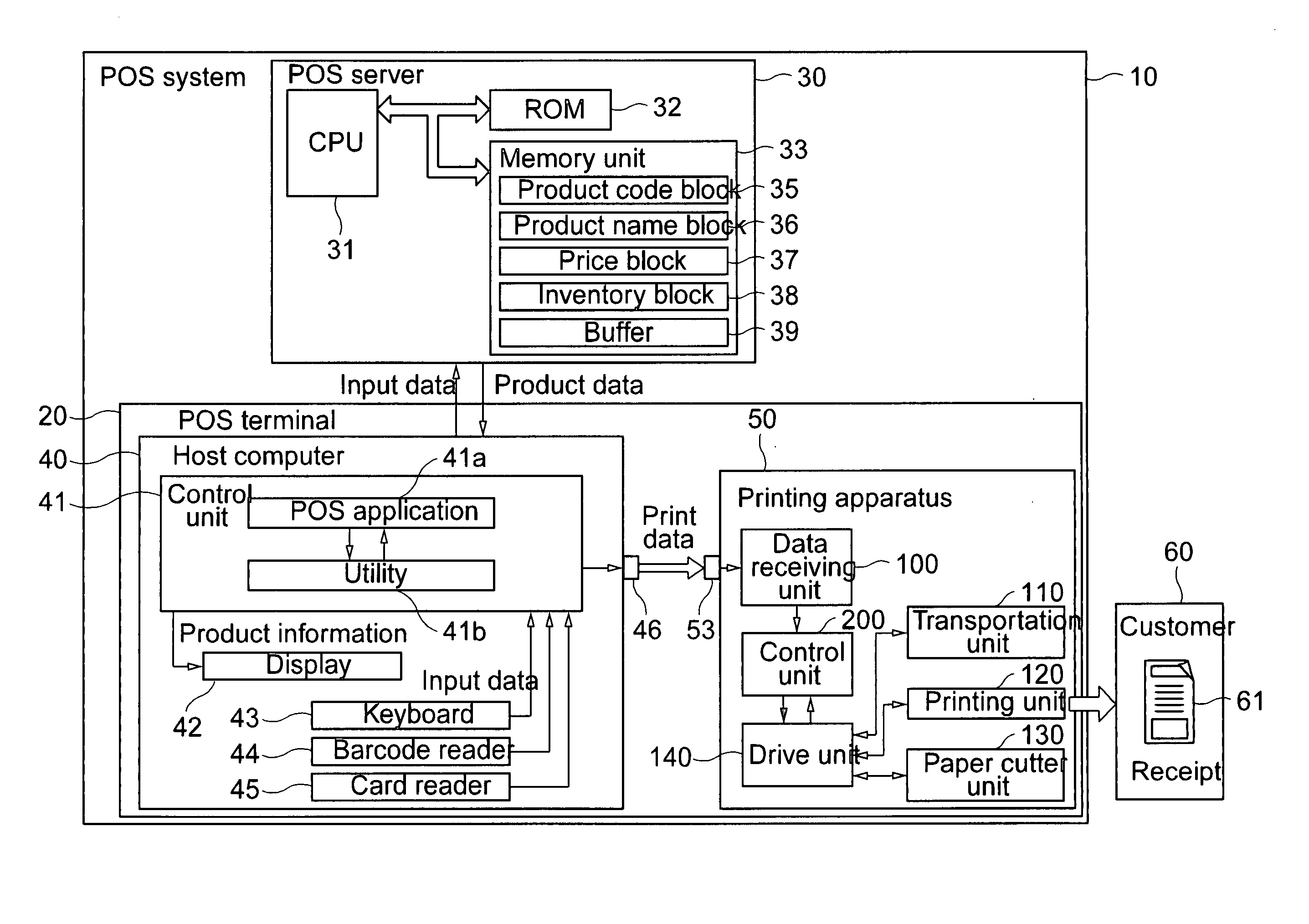
[0014] To make the receipt printing process more efficient, the header print data (typically a logo containing the store name, address, and a graphic, other than the transaction information print data and additional information print data) printed at the leading end of the next receipt before the transaction information print data is generally printed to the top of the next receipt before the transaction information print data is received. When the header print data is sent from the host computer while the paper cut command is delayed, the printing apparatus can determine that the received print data is not additional information print data by reading an identifier (such an identifier generally not contained in print data such as the header print data). The paper cut command can thus be executed before the print data is printed, and the receipt can be appropriately cut between the transaction information print data and header print data.
[0034] Furthermore, by using the transaction number as the identifier, the printing apparatus can determine to which transaction information print data the received additional information print data is to be added based on the identifier detected from the transaction information print data and the identifier detected from the additional information print data. Processing errors can thus be avoided by means of this evaluation.

Problems solved by technology

Especially, for the DOS, modifying the POS application itself is a complicated and expensive process.

Method used


Image

  • Printing apparatus, POS system and printing apparatus control method
  • Printing apparatus, POS system and printing apparatus control method
  • Printing apparatus, POS system and printing apparatus control method

Examples


second embodiment

[0100] the present invention is described below with reference to FIG. 6 to FIG. 9.

[0101] As shown in FIG. 6 this embodiment of the invention is based on a printing apparatus 50 in which the printing position and paper cutting position are separated. The problem solved by this embodiment of the invention is controlling printing while reducing the white space at the leading end of the receipt in this type of printing apparatus 50. Primarily the differences between this embodiment and the foregoing embodiment are described below.

[0102] As shown in FIG. 6 the printing position at which the print head 55 and platen 56 are disposed is on the upstream side in the receipt transportation direction, of the paper cutter position at which the receipt cutter 131 is disposed. The distance between both positions is identified as D. If the receipt is cut immediately after printing the transaction information print data, and the receipt will be cut somewhere within the print out of the transaction...

first embodiment

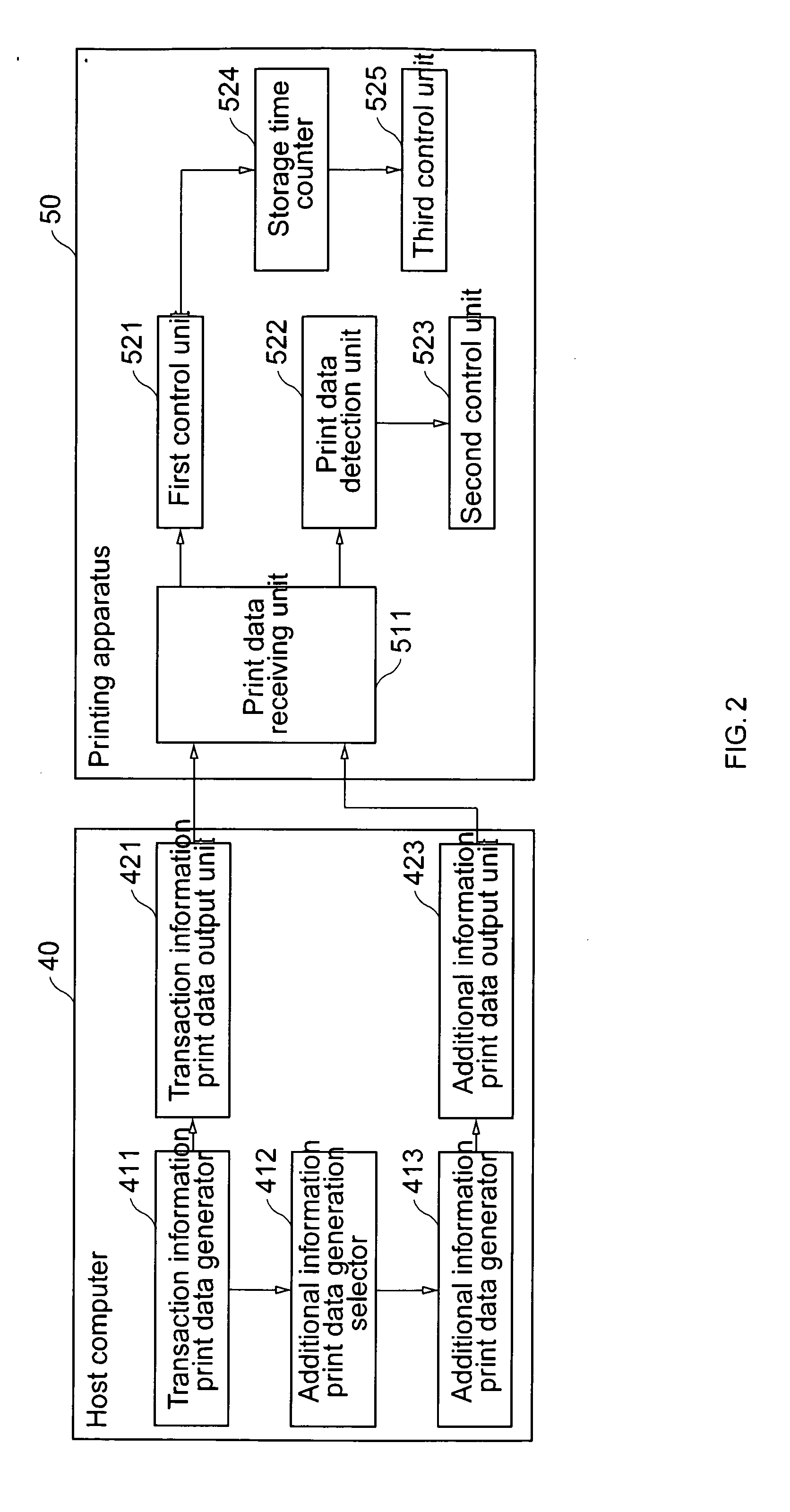
[0109] The header print data generator 431 and header print data output unit 441 can be rendered primarily by the POS application 41a or utility 41b. In addition, the transaction information print data generator 411, transaction information print data output unit 421, additional information print data generation selector 412, additional information print data generator 413, and additional information print data output unit 423 have the same function as in the foregoing first embodiment, and further description thereof is thus omitted here.

[0110] The printing apparatus 50 has a print data receiving unit 511, first control unit 541, print data detection unit 542, second control unit 543, and third control unit 544.

[0111] The first control unit 541 handles control when the print data receiving unit 511 receives transaction information print data.

[0112] The print data detection unit 542 determines the data type when print data is received while executing the paper cut command is delay...

third embodiment

[0133] the present invention is described next with reference to FIG. 10.

[0134] The host computer 40 sends transaction information print data and additional information print data to the printing apparatus 50 in the foregoing embodiments. This embodiment of the invention, however, adds an information-provider server 70 for generating and providing this additional information print data, and thus differs from the preceding embodiments in that the transaction information print data is sent from the host computer 40 and the additional information print data is sent from the information-provider server 70 to the printing apparatus 50.

[0135] In addition, a printer interface 600 (Universal Interface Board: UIB) having two ports 610 and 620 for connecting to the host computer 40 and information-provider server 70 is also removable installed to the printing apparatus 50, and the printing apparatus 50 thus acquires the print data through this printer interface 600.

[0136] For brevity only t...


PUM


Abstract

A printing apparatus and method for printing receipts and for controlling the cutting of each receipt in succession from a recording medium such as print paper at an appropriate position determined from the print data received from a host computer. The printing apparatus 50 prints first print data representing transaction information with a paper cut command appended thereto and second print data representing additional information from print data received from a host computer 40. A first control unit 521 prints the first print data and delays executing the paper cut command added to the first print data when first print data is received from the host computer. When print data is received while execution of the paper cut command is delayed, a print data detection unit 522 determines the type of print data received based on the presence or absence of an identifier in the received print data. If the received print data is recognized as second print data, a second control unit 523 prints the received second print data and then executes the paper cut command. If the received print data is determined not to be second print data, the second control unit 523 executes the paper cut command before printing the received print data.

Description

BACKGROUND OF THE INVENTION [0001] 1. Field of Technology [0002] The present invention relates to a printing apparatus for printing a receipt to print paper and cutting the receipt from the print paper in response to print data received from a computer with the print data including transaction information print data generated e.g. by a POS (point-of-sale) application running on a host computer with a paper cut command contained in the print data, and additional information print data that is added to the transaction information print data, and relates further to a POS system and a control method.0 [0003] 2. Description of Related Art [0004] Additional information, e.g. advertising information such as product advertisements and event announcements, is commonly added to and printed in addition to transaction information relating to purchased products and their purchase price information on customer receipts in supermarkets and other retailers as well as in fast food stores and other r...

Claims


Application Information

Patent Timeline
Patent Type & Authority Applications(United States)
IPC IPC(8): G07G1/12B26D1/08B26D5/30B41J29/38G07B1/00G06F3/12G07B5/02B41J11/70B41J11/26
CPCB26D1/085B26D5/30G06Q20/209G07B1/00G07B5/02
Inventor MINOWA, MASAHIRO
Owner SEIKO EPSON CORP
Learn More