
Multilayer graphic systems

a graphic system and multi-layer technology, applied in the field of multi-layer graphic systems, can solve the problems of system strain or tear, difficulty in solving problems, and difficulty in reducing the effect of printing efficiency, tearing, and reducing the effect of tearing

Active Publication Date: 2008-04-22
INSITE SOLUTIONS
View PDF4 Cites 14 Cited by
  • Summary
  • Abstract
  • Description
  • Claims
  • Application Information

AI Technical Summary

Benefits of technology

[0009]By employing a fabric substrate, the present invention overcomes many of the problems associated with prior art multilayer graphic systems. To begin with, the multilayer graphic systems of the present invention can be made very thin because the fabric substrates employed can be very thin. Although thin, the fabric substrates provide equal if not greater strength than the polymeric substrates employed in the prior art. As a result, the graphic articles of this invention can be shipped and applied or installed without deleteriously impacting the article. And, moreover, the articles can be efficiently removed without tearing. It has also advantageously been discovered that in those embodiments that employ graphic printing to provide the graphic system with a visible image, the fabric has proven to provide a substrate that can be efficiently printed on and yield a platform upon which high quality printing can be disposed.

Problems solved by technology

Where the layered graphic system is applied to horizontal surfaces, the graphic systems are subjected to many forces, such as pedestrian or automotive traffic, that can stretch or tear the system.
These problems are exacerbated by thicker graphic systems because the height of the system subjects the system to greater forces.
The problem is not easily solved, however, by decreasing the thickness of the substrate.
Thinner graphic systems, which have been prepared by decreasing the thickness of the polymeric substrate, result in a graphic system having less integrity.
This not only creates problems during usage, but also creates problems during removal.
Where the graphic system tears during removal, replacement is often difficult and inefficient.

Method used


Image

  • Multilayer graphic systems
  • Multilayer graphic systems

Examples


Embodiment Construction

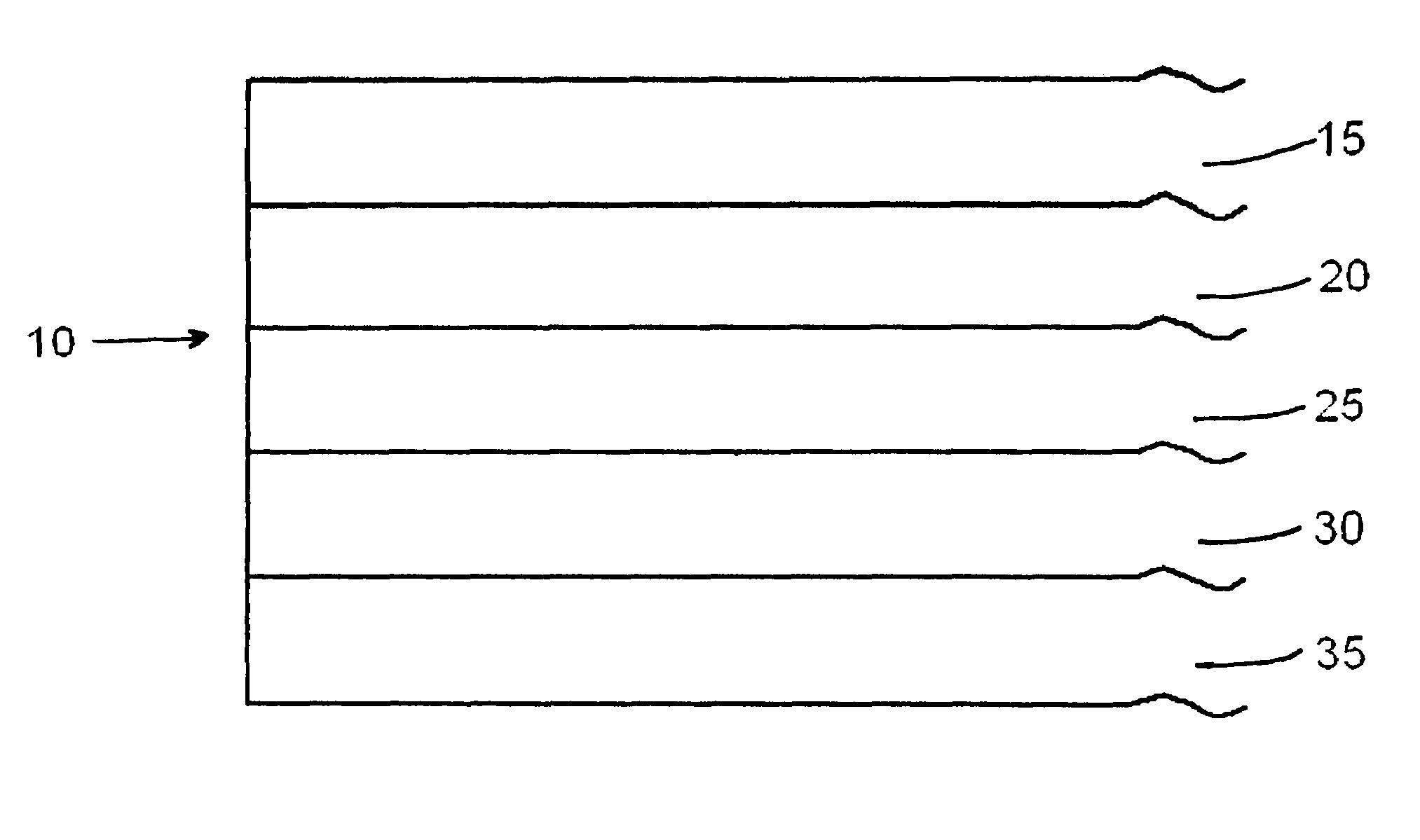
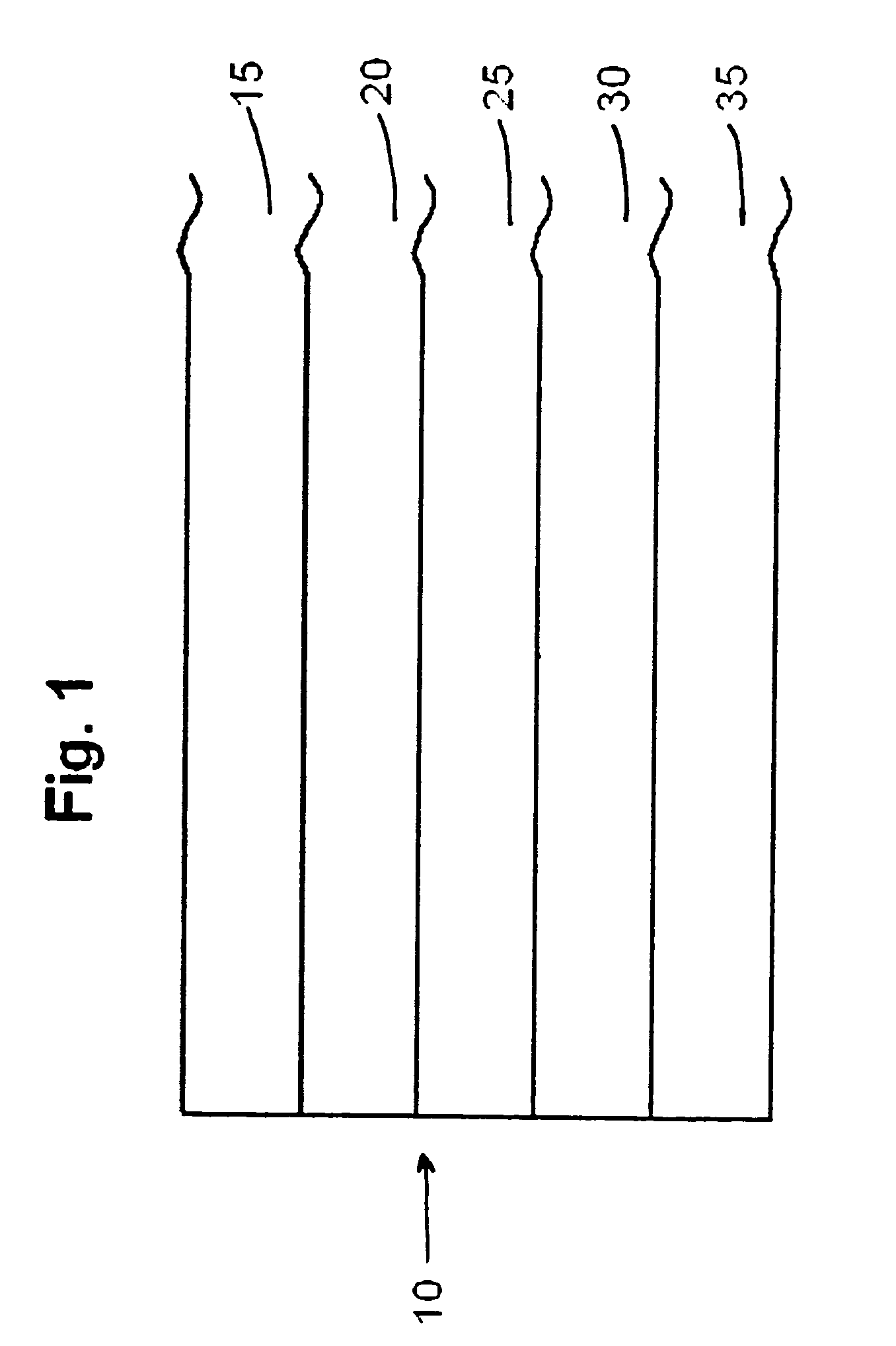
[0011]The preferred multilayer graphic article of the present invention is best described with reference to FIG. 1. Graphic article 10 includes fabric matrix or support 25 with image layer 20 disposed thereon. Protective coating 15, which may carry optional anti-skid particles, is disposed on image layer 20 to prevent damage to the image layer 20 from a variety of conditions that the graphic article 10 may be subjected to. Below and adhered to fabric matrix or support 25 is adhesive layer 30, which may carry optional release liner 35.

[0012]The matrices or supports in the practice of this invention are fabrics. Fabrics include those textile structures comprising mechanically interlocked fibers or filaments. These fibers or filaments can be woven or non-woven. In other words, woven fabrics include closely oriented warp and filler strands. In a preferred woven fabric, the warp and filler strands are at right angles to each other. The non-woven fabric includes those fibers or filaments ...


PUM

PropertyMeasurementUnit
thicknessaaaaaaaaaa
thicknessaaaaaaaaaa
thicknessaaaaaaaaaa

Abstract

A multilayer graphic article comprising (a) a fabric matrix or support having an upper and lower surface, (b) at least one image layer disposed on the upper surface of the fabric matrix or support, (c) a protective layer disposed over the at least one image layer, and, (d) an adhesive layer adhered to the lower surface of the fabric matrix or support.

Description

[0001]This application gains priority from U.S. Provisional Patent Application No. 60 / 419,692, filed on Oct. 18, 2002.BACKGROUND OF THE INVENTION[0002]Multilayer graphic systems are known. For example, U.S. Pat. No. 5,468,532 teaches a system whereby first and second color layers (i.e., a graphic print) are deposited on a polymeric substrate. A clear protective layer is deposited over the color layers to protect the color layers, and an adhesive layer is disposed below the substrate so that the substrate can be applied to the various surfaces. In a similar fashion, U.S. Pat. No. 6,180,228 teaches a multilayer graphic system that is particularly suited for outdoor use. This graphic system includes a polymeric base layer, an adhesive layer disposed below the base layer, and an image layer disposed above the base layer. The protective polymeric film is laminated to the image layer by using an adhesive laminate.[0003]These multilayered graphic systems can be applied to a number of subst...

Claims


Application Information

Patent Timeline
Patent Type & Authority Patents(United States)
IPC IPC(8): B32B3/00B32B27/00B32B5/02B32B7/12B32B9/00
CPCB32B27/00Y10T428/2843Y10T428/2848Y10T442/2041Y10T442/2861Y10T442/2049Y10T442/20G09F15/02
Inventor LOWE, CLIFFORD A.
Owner INSITE SOLUTIONS
Learn More