
Cell configuration method and system with minimum intercell interference and method for channel allocation therein

Inactive Publication Date: 2005-12-08
SAMSUNG ELECTRONICS CO LTD
View PDF3 Cites 18 Cited by
  • Summary
  • Abstract
  • Description
  • Claims
  • Application Information

AI Technical Summary

Benefits of technology

[0013] It is, therefore, an aspect of the present invention to provide a method for cell configuration in a mobile communication system capable of providing a mobile subscriber located at the boundary area between a serving cell and its adjacent cells with a minimum of intercell interference, thereby providing a stable communication service to the subscriber.
[0014] It is another aspect of the present invention to provide a channel allocation system capable of providing a mobile subscriber located at the boundary area between a serving cell and its adjacent cells with a minimum of intercell interference, and a method for channel allocation, thereby providing a stable communication service to the subscriber.
[0015] It is still another aspect of the present invention to provide a system and method for cell configuration adapted to providing a stable hand-off operation in a mobile communication system and a channel allocation method applicable in the system.
[0016] To achieve the above and other aspects of the present invention, there is provided a cell configuration method for minimizing intercell interference between a serving cell for a mobile terminal and adjacent cells of the serving cell in a mobile communication system having a plurality of cells, including the steps of determining a number of safety channels to be assigned to each of the plurality of cells; and providing the adjacent cells around the serving cell with at least one additional shared safety channel other than the safety channel originally assigned to the each cell.
[0018] According to a third aspect of the present invention, there is provided a method for minimizing the intercell interference between cells in a mobile communication system having a serving cell associated a mobile terminal located in the cell area, the serving cell being assigned with a safety channel, and having a plurality of adjacent cells around the serving cell, the adjacent cells each having at least one additional shared safety channel other than the safety channel originally assigned to the serving cell, including the steps of sending a request for safety channel allocation to a base station of the serving cell in case the intercell interference from the adjacent cell during communication with the serving cell is more than a predetermined threshold value; assigning to the mobile terminal the shared safety channel of the adjacent cells except their own original safety channels, when the base station of the serving cell has received the request for safety channel allocation from the mobile terminal; and wirelessly communicating through the safety channel assigned by the base station.

Problems solved by technology

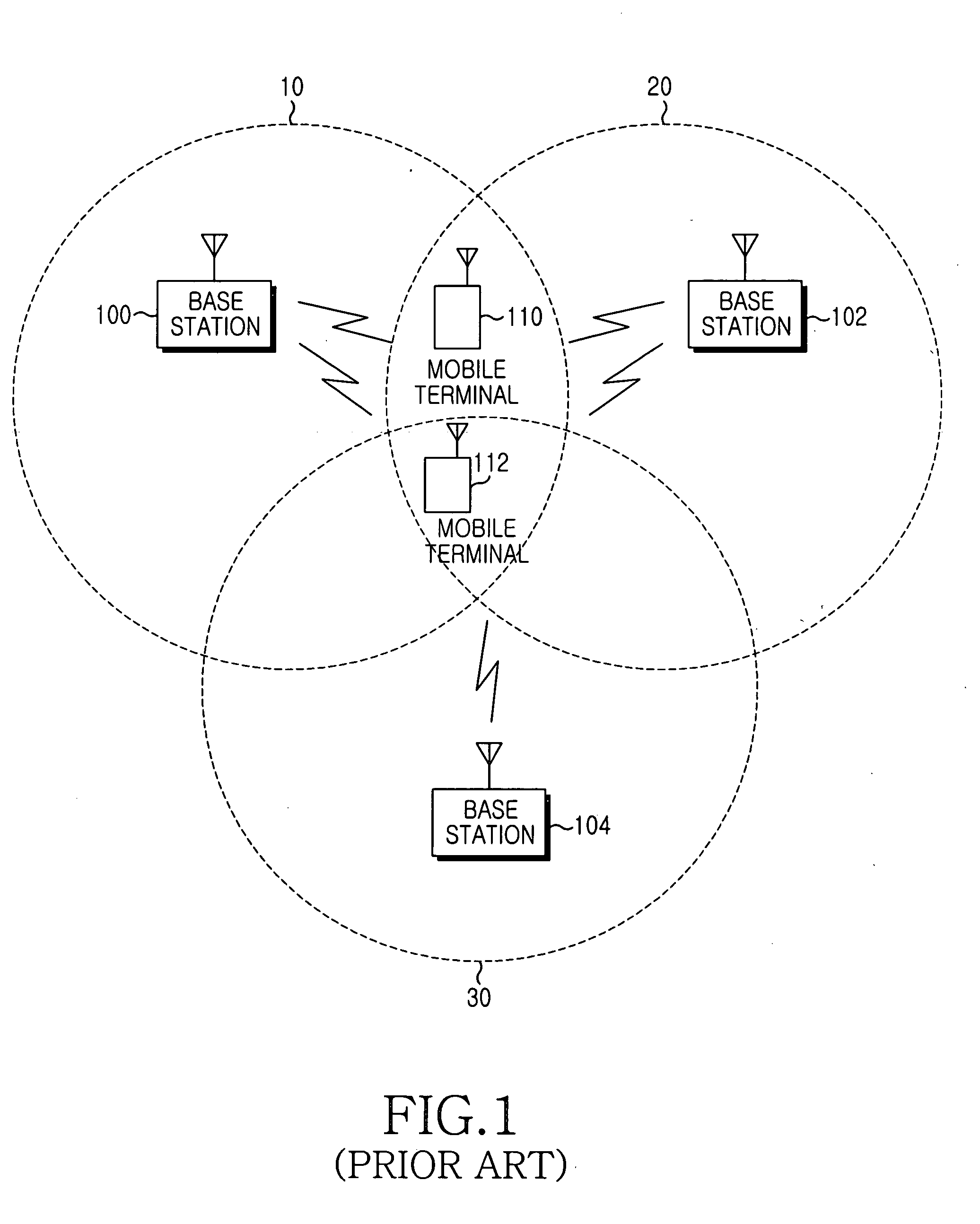
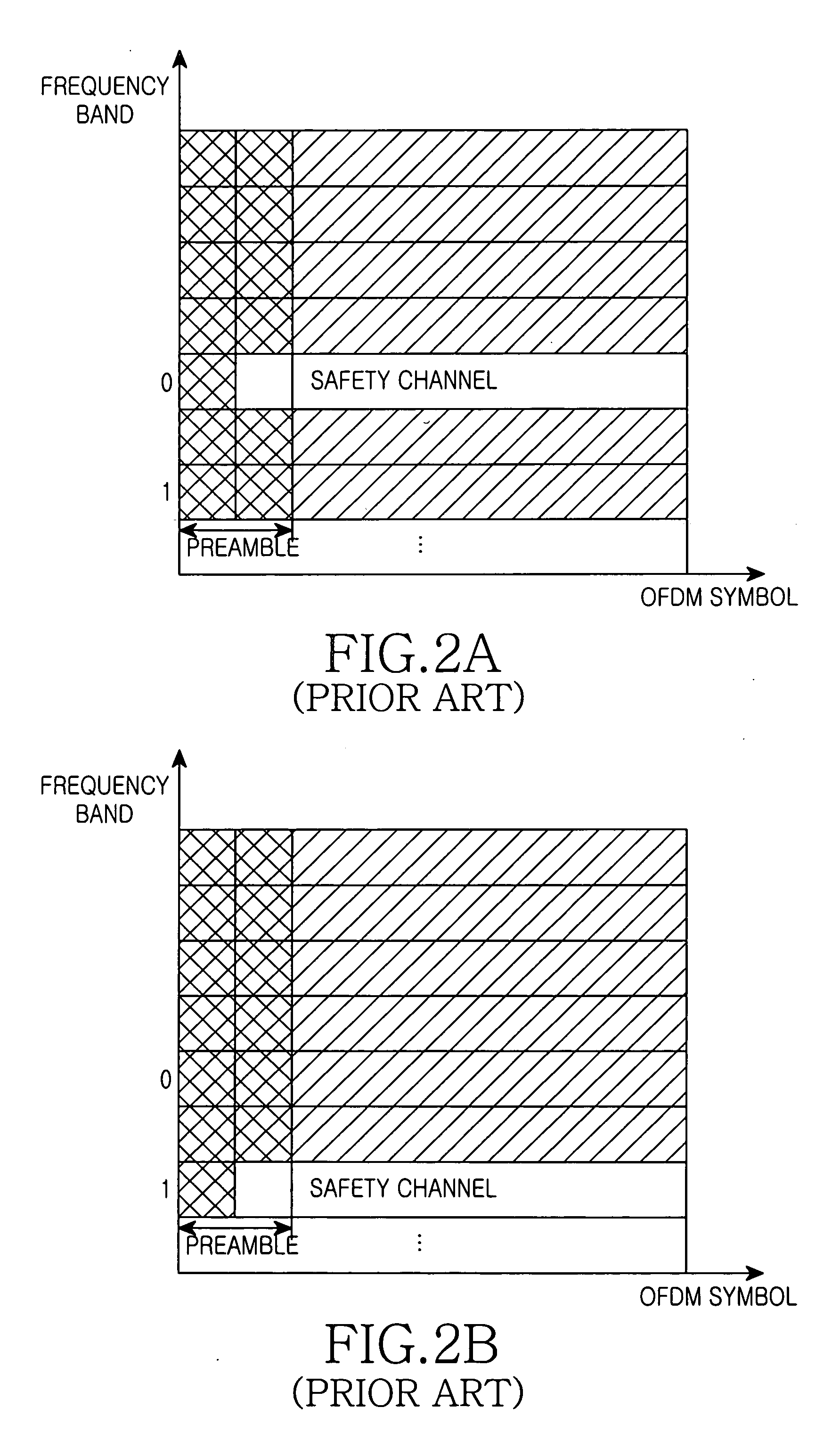
Further, if the interference from the adjacent cells is at a significant level, then the mobile terminal may be substantially unable to search for a correct safety channel frequency band while scanning preambles punctured in any of the received frames for finding the safety channel.

Method used


Image

  • Cell configuration method and system with minimum intercell interference and method for channel allocation therein
  • Cell configuration method and system with minimum intercell interference and method for channel allocation therein
  • Cell configuration method and system with minimum intercell interference and method for channel allocation therein

Examples


first embodiment

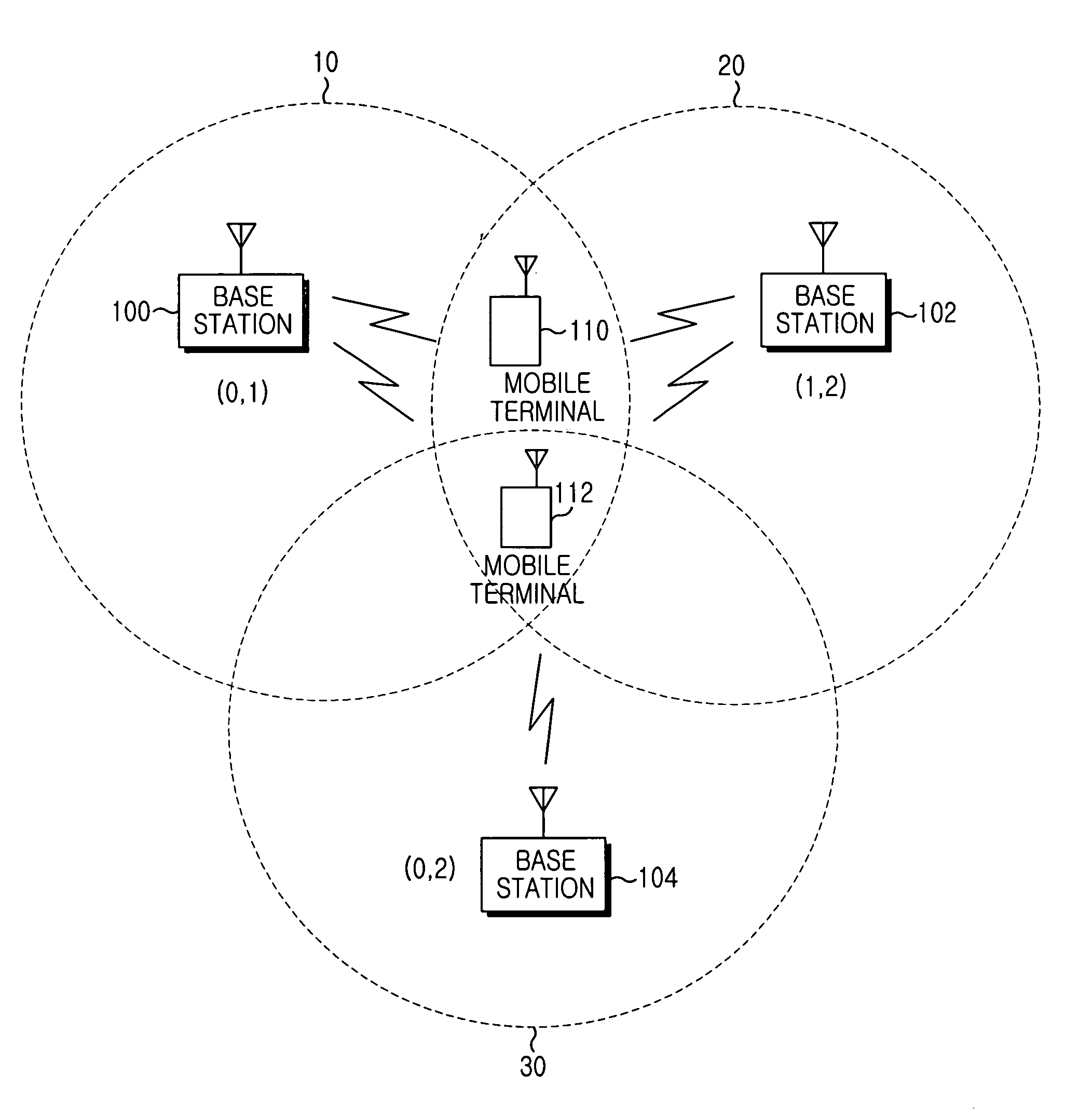
[0035] Now, referring to FIG. 6, a description is made of the control sequence for carrying out with the least possible interference from any adjacent cells to a mobile terminal located at a cell boundary area in the mobile communication system with the aforementioned cell configuration. FIG. 6 shows a flow chart diagram for controlling the channel allocation between the mobile terminal and the base station in accordance with the present invention. The mobile terminal is assumed to be terminal 112 affected by the interference applied from three cells as shown in FIG. 3, but the operation will be the same for terminal 110.

[0036] While the mobile terminal 112 is communicating with the base station 100 of the serving cell 10 in step 600, the Carrier to Interference (C / I) value in the serving cell 10 is checked in step 602 to determine if it is not greater than a specified threshold value. Thereafter, if it is not greater than the threshold value, then the mobile terminal 112 transmits ...

second embodiment

[0039] Referring now to FIG. 7, the control sequence for carrying out the optimum channel allocation between the mobile terminal and the base station in the mobile communication system according to the present invention will be described.

[0040] While the mobile terminal 112 is communicating with the base station 100 of the serving cell 10 in step 700, the C / I value of the serving cell 10 is checked in step 702 to determine if it is less than a specified threshold value. Thereafter, if it is not greater than the threshold value, the C / I value is transmitted to the base station 100 in step 704 in order to request a channel allocation. The mobile terminal 112 transmits the C / I value to the base station 100 to make a request for safety channel allocation to prevent any interference from the adjacent cells during communication. In step 706, the base station 100 having received this C / I value assigns to the mobile terminal 112 bins of the safety channel band other than the safety channels...


PUM


Abstract

A cell configuration method and system and a channel allocation method for the system are disclosed for minimizing the influence of intercell interference between cells in a mobile communication system capable of providing a mobile subscriber with a stable communication service, by determining a number of safety channels to be assigned to each of the plurality of cells, and providing the adjacent cells around the serving cell with at least one additional shared safety channel other than the safety channel originally assigned to the each cell.

Description

CLAIM OF PRIORITY [0001] This application claims benefit under 35 U.S.C. §119 from an application entitled “A Method And System With Cell Configuration For Minimizing Intercell Interference And A Method For Channel Allocation Therein” earlier filed in the Korean Industrial Property Office on Jun. 4, 2004 and assigned Serial No. 2004-40774, the contents of which are hereby incorporated by reference. BACKGROUND OF THE INVENTION [0002] 1. Field of the Invention [0003] The present invention relates generally to cell configuration and channel allocation with a minimum of intercell interference in a mobile communication system, and in particular, to a method and system configured to provide a mobile subscriber located at a cell boundary with a more stable communication service with a reduction of intercell interference by an adjacent cell and such a channel allocation method used therein. [0004] 2. Description of the Related Art [0005] Mobile Internet communication systems are generally c...

Claims


Application Information

Patent Timeline
IPC IPC(8): H04W16/02H04W16/12H04W72/04
CPCH04W16/02H04W16/12H04W72/0413H04W72/082H04W72/21H04W72/541
Inventor WON, JONG-HYUNPARK, YUN-SANGCHANG, JAE-HWANHYON, TAE-INKIM, YUN-SUNG
Owner SAMSUNG ELECTRONICS CO LTD
Learn More