Ankle-foot orthosis

a technology for ankles and feet, applied in the field of ankle-foot orthosis, can solve the problems of limited ankle-foot orthoses, unsatisfactory orthoses, users with reduced mobility, and decreased quality of life, and achieve the effects of increasing or narrowing the gap between the two, increasing and reducing the stiffness of the orthosis

Active Publication Date: 2005-12-08
RONAN REYNOLDS +2
View PDF48 Cites 18 Cited by
  • Summary
  • Abstract
  • Description
  • Claims
  • Application Information

AI Technical Summary

Benefits of technology

[0017] According to an ninth aspect of the invention, the ankle-foot orthosis further includes an adjustment mechanism provided between the calf shell and an uppermost segment for expanding or narrowing the width of the gap therebetween. Expanding the width of the gap in which the adjustment mechanism is provided correspondingly narrows the widths of the gaps therebelow, compresses the spacers disposed between opposing surfaces defining the gaps, and increases the stiffness the orthosis. Narrowing the width of the gap in which the adjustment mechanism is provided correspondingly expands the widths of the gaps therebelow, decompresses the spacers disposed between the opposing surfaces defining the gaps, and decreases the stiffness of the orthosis. In one embodiment, the adjustment mechanism is a threaded rod and locknut combination. Alternately, the adjustment mechanism is a twist draw mechanism.
[0018] According to a tenth aspect of the present invention, an alternate embodiment of the ankle-foot orthosis includes a strut member, a calf shell disposed at an upper end of the strut member, a foot shell disposed at a lower end strut member, and a plurality of segments disposed between the calf shell and the foot shell along front and back surfaces of the strut member forming gaps therebetween. In dorsiflexion, a width of the gaps at front edges thereof decrease until the front edges of the segments contact each other, increasing dorsiflexion stiffness and creating a gradual dorsiflexion stop. In plantar flexion, a width of the gaps at back edges thereof decreases, increasing plantar flexion stiffness and creating a gradual plantar flexion stop.

Problems solved by technology

Presently available ankle-foot orthoses are limited, because the orthoses cannot be customized to specifically address a specific user's dorsiflexion and plantar flexion stiffness needs to any significant or acceptable degree.
As a result, for users needing an orthosis that matches the dorsiflexion stiffness of the normal human foot, the presently available orthoses are unsatisfactory, leaving some users with reduced mobility and a decreased quality of life.
A further drawback of current orthoses relates to plantar flexion stiffness.
However, currently available orthoses, other than some articulated orthoses, have a plantar flexion that is much higher, making walking and general mobility more difficult, and decreasing the user's quality of life.
Consequently, the stops cause the transmission of large forces into the user's body when the stops engage, and, over time, the relatively large forces damage a user's knee and hip joints.

Method used


Image

  • Ankle-foot orthosis
  • Ankle-foot orthosis
  • Ankle-foot orthosis

Examples


first embodiment

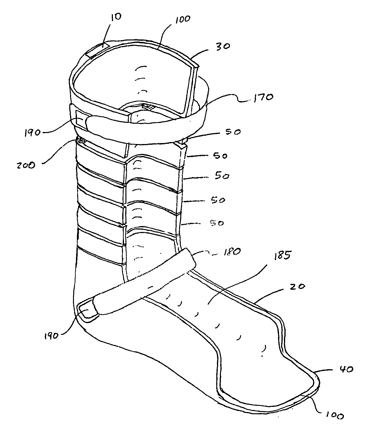
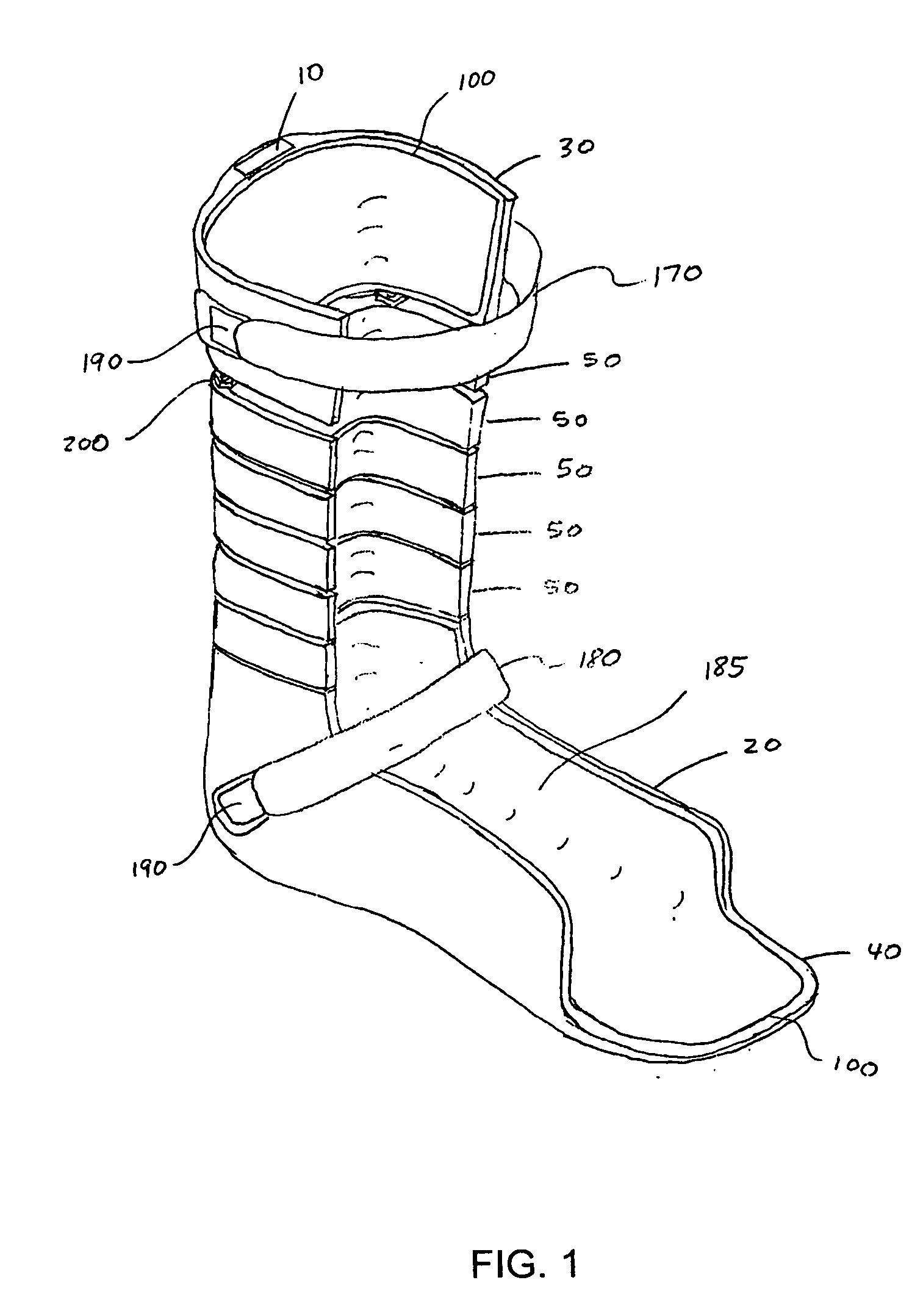
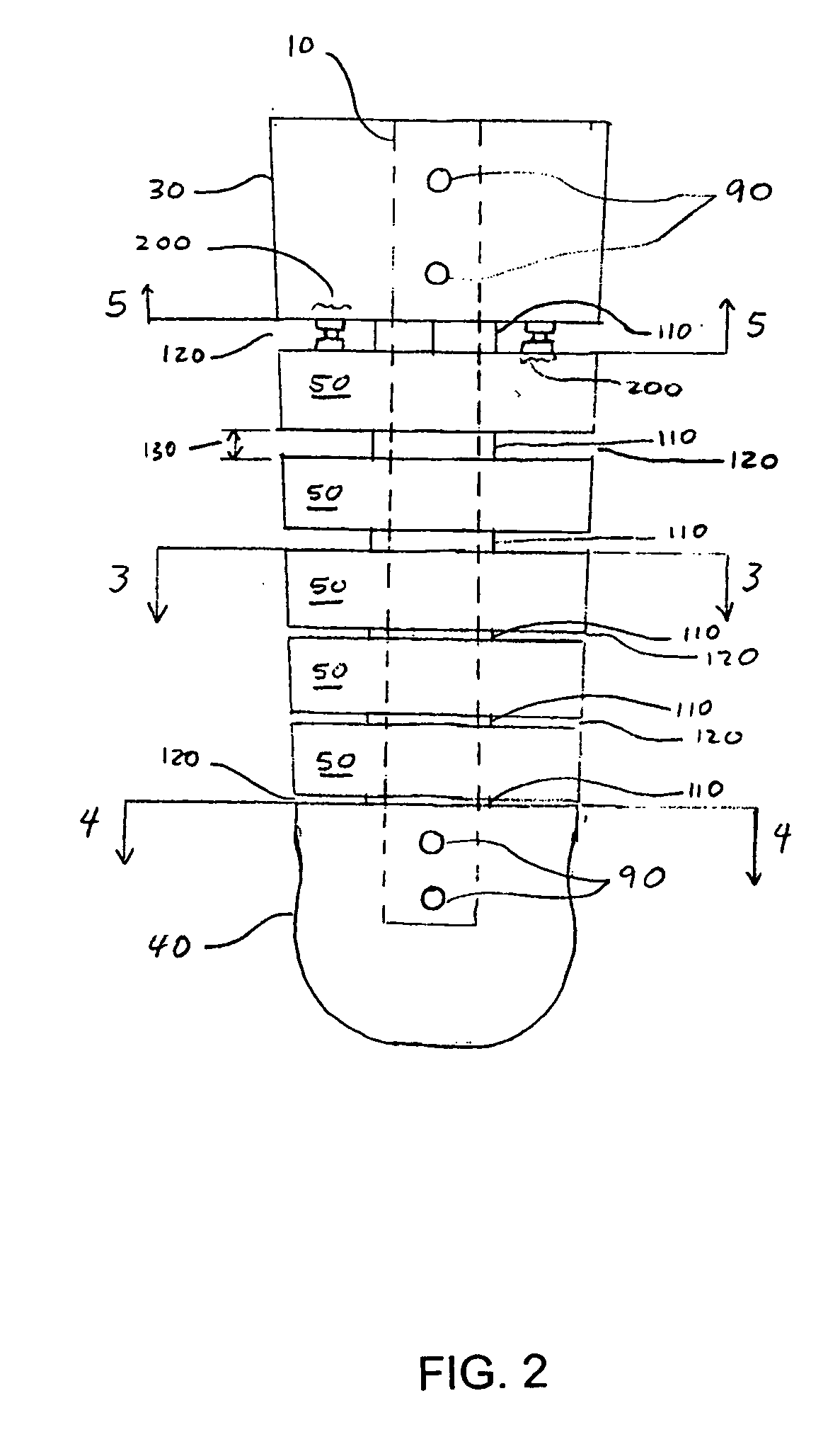
[0056]FIGS. 1 and 2 illustrate an orthosis according to the present invention. The orthosis includes a strut 10 having a foot shell 20 attached to a lower end and a calf shell 30 attached to an upper end. Optionally, the foot shell 20 may include a toe extension 40 for supporting a user's toes, if such support is needed by the user. A plurality of segments 50 extends from the calf shell 30 to the foot shell 20 along a vertical length of the strut 10. In a preferred embodiment, the foot shell 20, calf shell 30, and segments 50 have U-shaped cross-sections. Further, the orthosis includes an adjustment mechanism 200 for adjusting the stiffness of the orthosis, which is described in more detail below.

[0057] Referring to FIG. 3, the segment 50 includes a passageway 60 extending vertically through a back portion thereof, a pair of front edges 160, and a back edge 300. The passageway 60 is configured to accommodate a portion of the strut 10 passing therethrough. As shown in FIG. 4, the foo...

second embodiment

[0074]FIGS. 10 and 11 illustrate the adjustment mechanism 200′, which includes a twist draw mechanism 230. The mechanism 230 is essentially a twist draw latch, sometimes referred to as a butterfly latch. In one embodiment of the mechanism 230, a rotatable member 240 causes a pin 250 attached at a radius of the rotatable member 240 to slide within a slots 260 and 270 provided in a frame member 280 and a slide 290, respectively. The slot 260 restricts the amount of rotation that rotatable member 240 may rotate. The slide 290 is constrained horizontally but not vertically. Therefore, as the pin 250 follows a circular motion of the rotatable member 240 within slot 260, the pin 250 freely moves horizontally within the slot 270, forcing the slide 290 to move vertically within the frame member 280. As a result, the circular motion is translated into a purely vertical motion. Consequently, when the mechanism 230 is attached to the posterior of the calf shell 30, for example, a lower edge of...

third embodiment

[0078] the present invention is illustrated in FIG. 13. In such an embodiment, a hinge 310 is provided between a foot shell 320 and a lowermost segment 330, wherein one end of the hinge 310 is inserted into an opening 340 extending vertically through a posterior portion of a foot shell 320 and a second end is inserted into a passageway 350 extending vertically through a lower portion of the lowermost segment 330. A lower end of a strut 360 occupies an upper portion of the passageway 350 in the lowermost segment 330. Alternately, the hinge 310 can be located between any two adjacent segments 330. The hinge 310 can also be disposed between a calf shell 370 and the uppermost segment 330. Further, it is within the scope of the present invention that more than one hinge 310 be used.

[0079] The hinge 310 eliminates essentially all stiffness of the orthosis in both dorsiflexion and plantar flexion at a location where the hinge 310 is disposed, until, in dorsiflexion, front edges 400 of the ...


PUM


Abstract

An ankle-foot orthosis for aiding or enhancing a user's foot and ankle movement, wherein the orthosis comprises at least one strut member, a calf shell, a foot shell, and a plurality of segments. Gaps formed between adjacent segments, an uppermost segment and the calf shell, and a lowermost segment and the foot shell have gap widths, wherein gaps at a higher location have larger gap widths than those at a lower location. Therefore, in dorsiflexion, the gaps close in series from bottom to top, gradually increasing the orthosis stiffness, creating a progressive dorsiflexion stop, and decreasing the magnitude of loads transferred into the user. In plantar flexion, the gaps similarly decrease in series from bottom to top, gradually increasing the orthosis stiffness, creating a progressive plantar flexion stop, and decreasing the magnitude of loads transferred into the user.

Description

CROSS-REFERENCE TO RELATED APPLICATION [0001] This application claims the benefit of U.S. Provisional Application No. 60 / 564,728, filed Apr. 23, 2004.STATEMENT REGARDING FEDERALLY SPONSORED RESEARCH [0002] The U.S. Government has a paid-up license in this invention and the right in limited circumstances to require the patent owner to license others on reasonable terms as provided for by the terms of Grant No. H133E003001 awarded by the U.S. Department of Education.BACKGROUND OF THE INVENTION [0003] 1. Field of the Invention [0004] The present invention relates to an improved ankle-foot orthosis for supporting the foot and ankle of a user. The orthosis of the present invention assists the user in plantar flexion and / or dorsiflexion extension of the user's foot while simultaneously controlling medial and lateral ankle stiffness as well as torsion of the ankle in the coronal plane. [0005] 2. Discussion of Related Art [0006] Presently available ankle-foot orthoses are limited, because t...

Claims


Application Information

Patent Timeline
Patent Type & Authority Applications(United States)
IPC IPC(8): A61F5/00A61F5/01
CPCA61F5/0127A61F2005/0141
Inventor REYNOLDS, RONANWEBER, GUILLERMO GUSTAVOWEBER, ROGERLANDSBERGER, SAMUEL
Owner RONAN REYNOLDS
Why Eureka
Try Eureka