Injection device

a technology of injection device and syringe, which is applied in the direction of intravenous device, automatic syringe, infusion needle, etc., can solve the problems of undesirable effects, adverse consequences, and inability to ensure that the delatch mechanism will enable the retraction of syringe and needl

Inactive Publication Date: 2005-12-08
ETHICON ENDO SURGERY INC
View PDF2 Cites 129 Cited by
  • Summary
  • Abstract
  • Description
  • Claims
  • Application Information

AI Technical Summary

Benefits of technology

[0034] This provides a convenient and advantageous arrangement by which the first and second coupling elements can move relative to each other.
[0035] Inward deflection of the resilient arms may be achieved by means of a collar that is moveable within the housing. Movement of the collar allows it to be released from a first positi

Problems solved by technology

In practice, all of these proposals suffer a problem that, owing to a stack up of tolerances of the various manufactured components of the assembled device (the dimensions of all manufacture components vary around a mean), it cannot be assured that the delatch mechanism will enable retract

Method used


Image

  • Injection device
  • Injection device
  • Injection device

Examples


Embodiment Construction

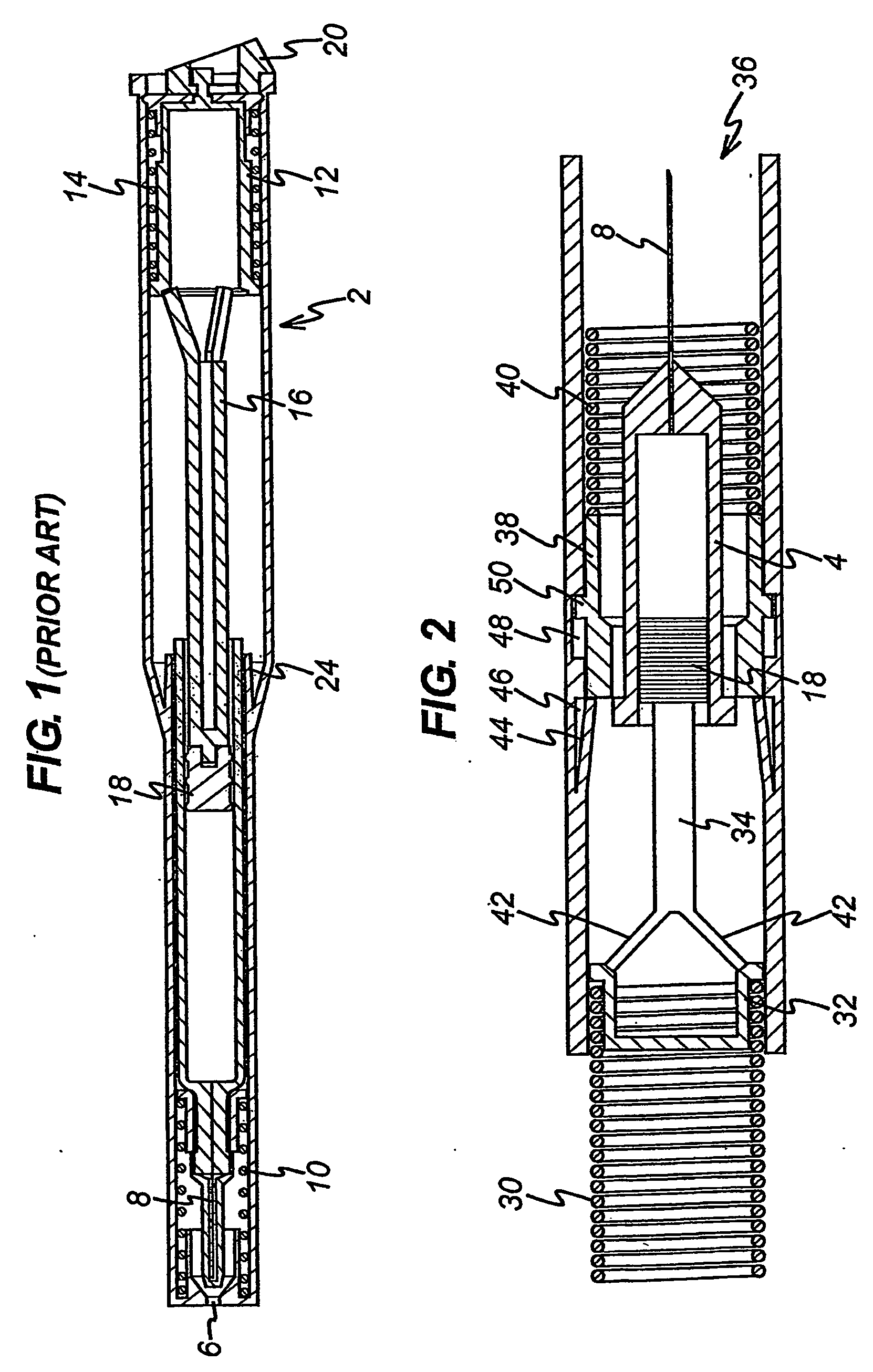
[0058] The present invention can be embodied in any suitable outer housing such as illustrated in FIG. 1, in particular having an opening 6 in its end through which the needle 8 of a syringe 4 may extend and a release mechanism 20 at its opposite end for releasing a spring 14 for deploying and emptying the contained syringe.

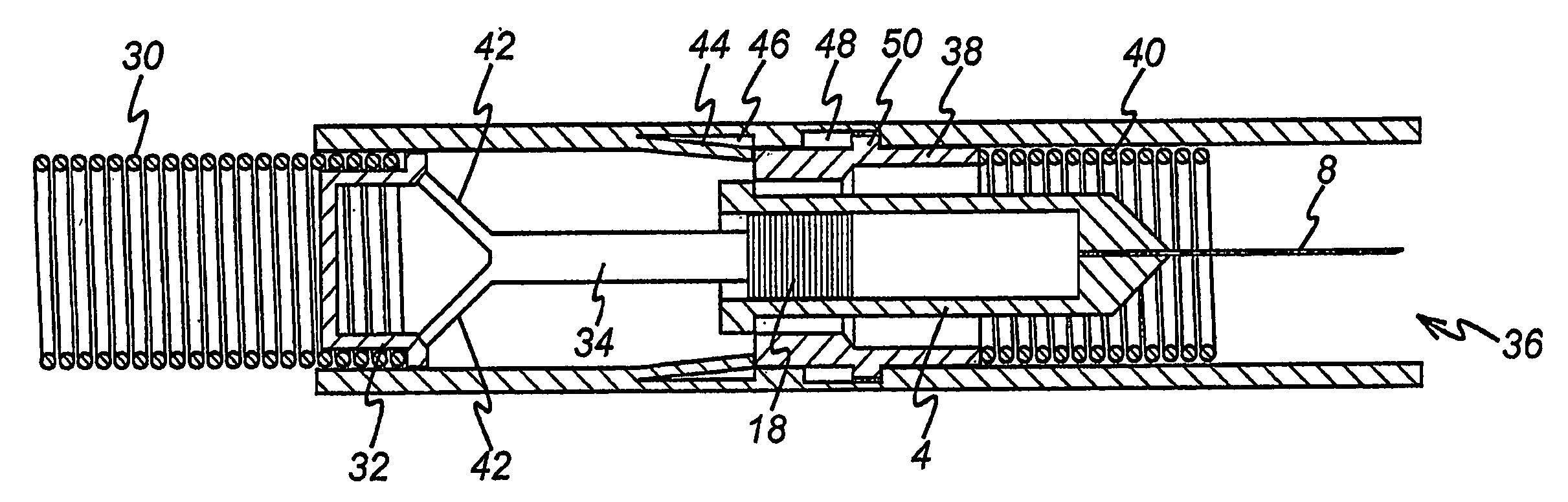
[0059]FIG. 2 illustrates schematically the key components of a preferred embodiment for use in a preferred housing.

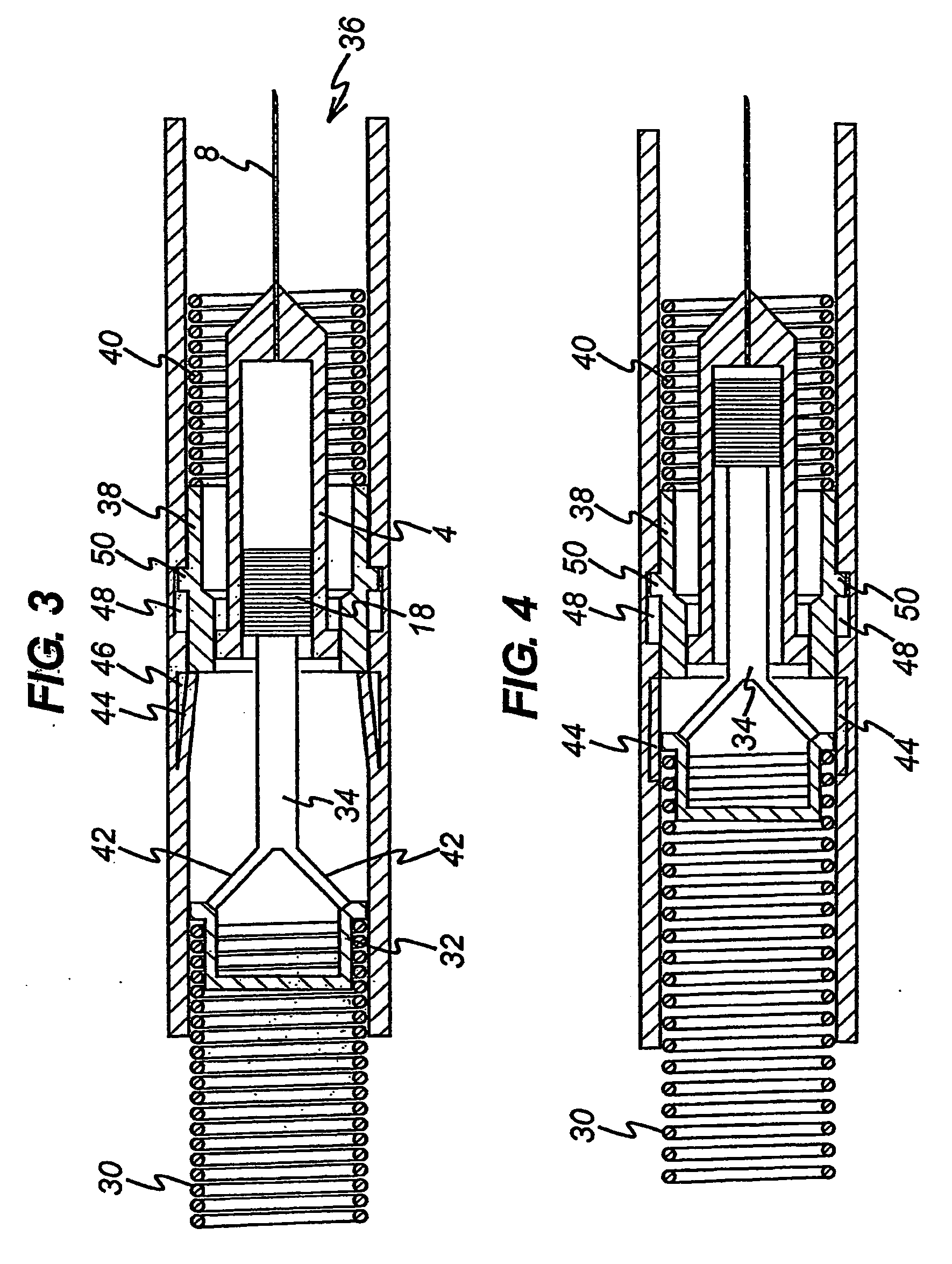
[0060] A drive spring 30 engages with a first coupling element 32, itself providing drive to a second coupling element 34. Thus, the drive spring 30 here acts as the motion-developing means for the injection device. Alternative motion-developing means could be used, for example a pneumatic piston operated by a compressed gas canister or the actuator of a solenoid in an electrically powered device. The second coupling element 34 is provided to engage the dispensing piston 18 of a syringe 4 in the device. Thus, when the coupling elements 32, 34 are r...


PUM


Abstract

An injection device including a housing for containing a syringe having a bore extending from an end surface, a needle communicating with the bore through the end surface and a dispensing piston movable in said bore towards said end surface so as to expel the contents of the syringe through the needle, the housing having an opening at one end through which the needle may extend, a resilient member for biassing the syringe and the needle inwardly off the housing, a first coupling element moveable towards said one end so as to move the needle of the syringe out of the opening and to move the dispensing piston of the syringe towards the end surface, a mechanism operable to release the syringe such that the needle moves inwardly off the housing, a drive coupling for extending from said first coupling element to the dispensing piston of the syringe so as to transfer movement of said first coupling element to the dispensing piston wherein the mechanism is triggered to release the syringe and includes components to delay release of the syringe until a predetermined period after being triggered such that it can be ensured that the dispensing piston reaches the end surface before the syringe is released and/or the mechanism includes an inertial mass moveable with the first coupling element and drive coupling and a release member actuable by the inertial mass to release the syringe such that when the dispensing piston releases the end surface of the syringe and the first coupling element and drive coupling stop moving, the inertial mass continues to move so as to actuate the release member to release the syringe.

Description

CROSS REFERENCE TO RELATED APPLICATION [0001] This application is a U.S. Non-Provisional Patent Application of International Publication No. WO 2004 / 054645 A2 filed on Dec. 17, 2003; GB Patent Application Serial No. 0325596.5 filed Nov. 3, 2003 which claims priority from GB Patent Application Serial No. 0229404.9 filed on Dec. 17, 2002 on which is hereby incorporated herein by reference. FIELD OF THE INVENTION [0002] The present invention relates to an injection device, in particular an injection device which, having dispensed the contents of a syringe, automatically retracts the needle of the syringe. BACKGROUND OF THE INVENTION [0003] As illustrated in FIG. 1, the prior art devices include a housing 2 in which a syringe 4 is contained. The housing 2 includes an opening 6 through which the needle 8 of the syringe 4 may extend. A retraction spring 10 biases the syringe 4 away from the opening 6. The device also includes a drive element 12 which is biased by a spring 14 to drive a co...

Claims


Application Information

Patent Timeline
IPC IPC(8): A61M5/20A61M5/315A61M5/32
CPCA61M5/2033A61M5/326A61M2005/206A61M2005/3143A61M2005/31516A61M5/16804A61M5/20A61M5/3234A61M5/168A61M5/32
Inventor HARRISON, NIGEL DAVIDBRADY, MATTHEW JAMESBERMAN, GREGORYJOHNSTON, DAVID MAXWELLHABESHAW, ROSEMARY LOUISE
Owner ETHICON ENDO SURGERY INC
Why Eureka
Try Eureka