Method and apparatus for mapping a data model to a user interface model

a data model and user interface technology, applied in the field of forms, can solve the problems of increasing complexity of ui technologies, cell phones, and other ui technologies, and laborious tasks for software developers to develop and maintain a large number of forms

Inactive Publication Date: 2005-12-08
MICROSOFT TECH LICENSING LLC
View PDF18 Cites 39 Cited by
  • Summary
  • Abstract
  • Description
  • Claims
  • Application Information

AI Technical Summary

Benefits of technology

[0010] The data model can be any of a variety of model types having datum of differing datum types. For example, the data model can be a database, a table, an entity, an object, etc. In embodiments in which the data model is mapped to a logical control model using a first declarative map, the first declarative map is used to map each of the datum types in the model to one of multiple logical controls available for use in the logical control model. The logical controls, and thus the logical model, are free from dependencies to any specific display target or platform.

Problems solved by technology

Developing and maintaining a large number of forms has traditionally been a labor-intensive task for software developers.
In the near future, personal digital assistant (PDA), cell phone, and other UI technologies will be adding to complexity.

Method used


Image

  • Method and apparatus for mapping a data model to a user interface model
  • Method and apparatus for mapping a data model to a user interface model
  • Method and apparatus for mapping a data model to a user interface model

Examples


Embodiment Construction

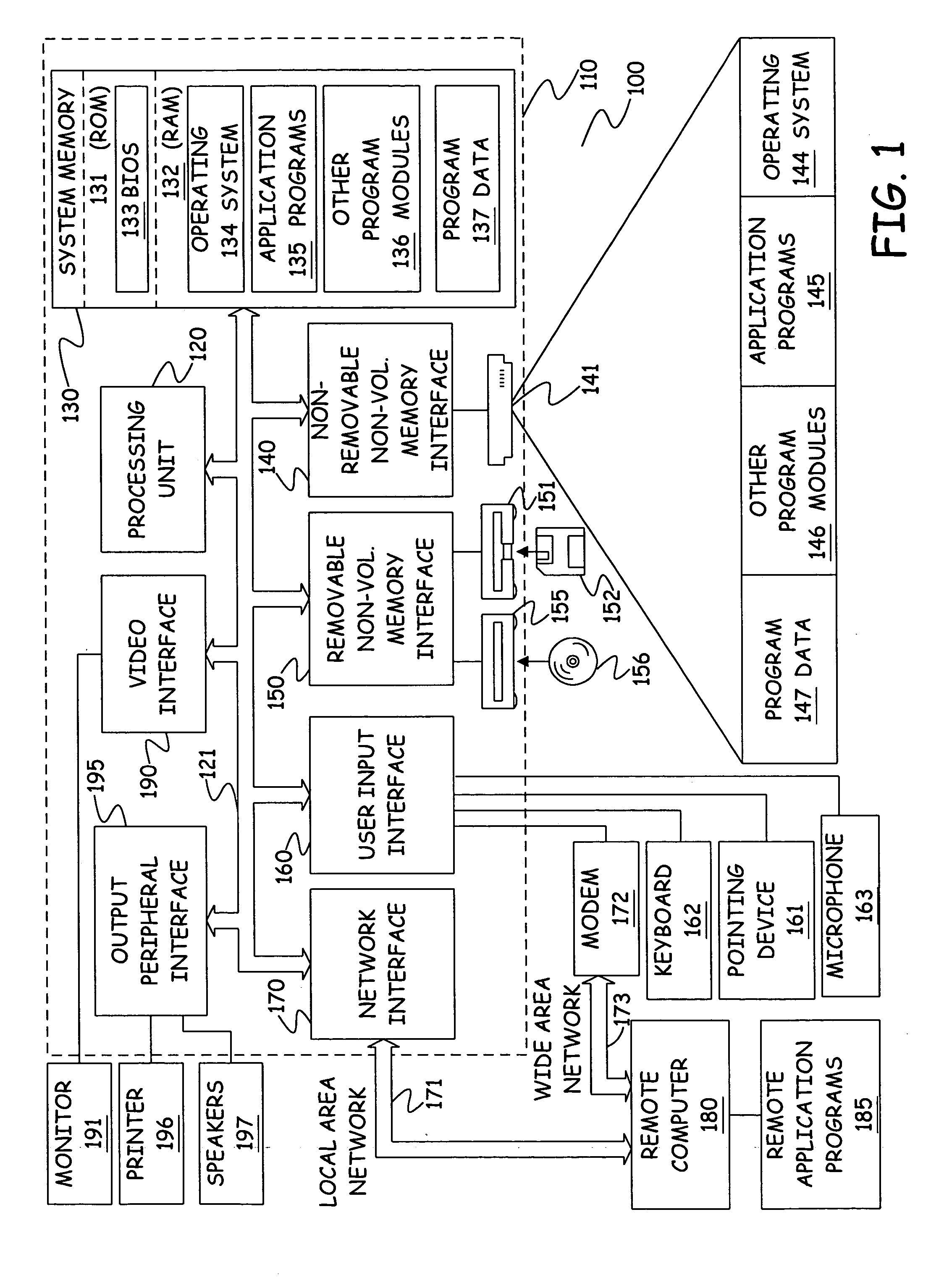
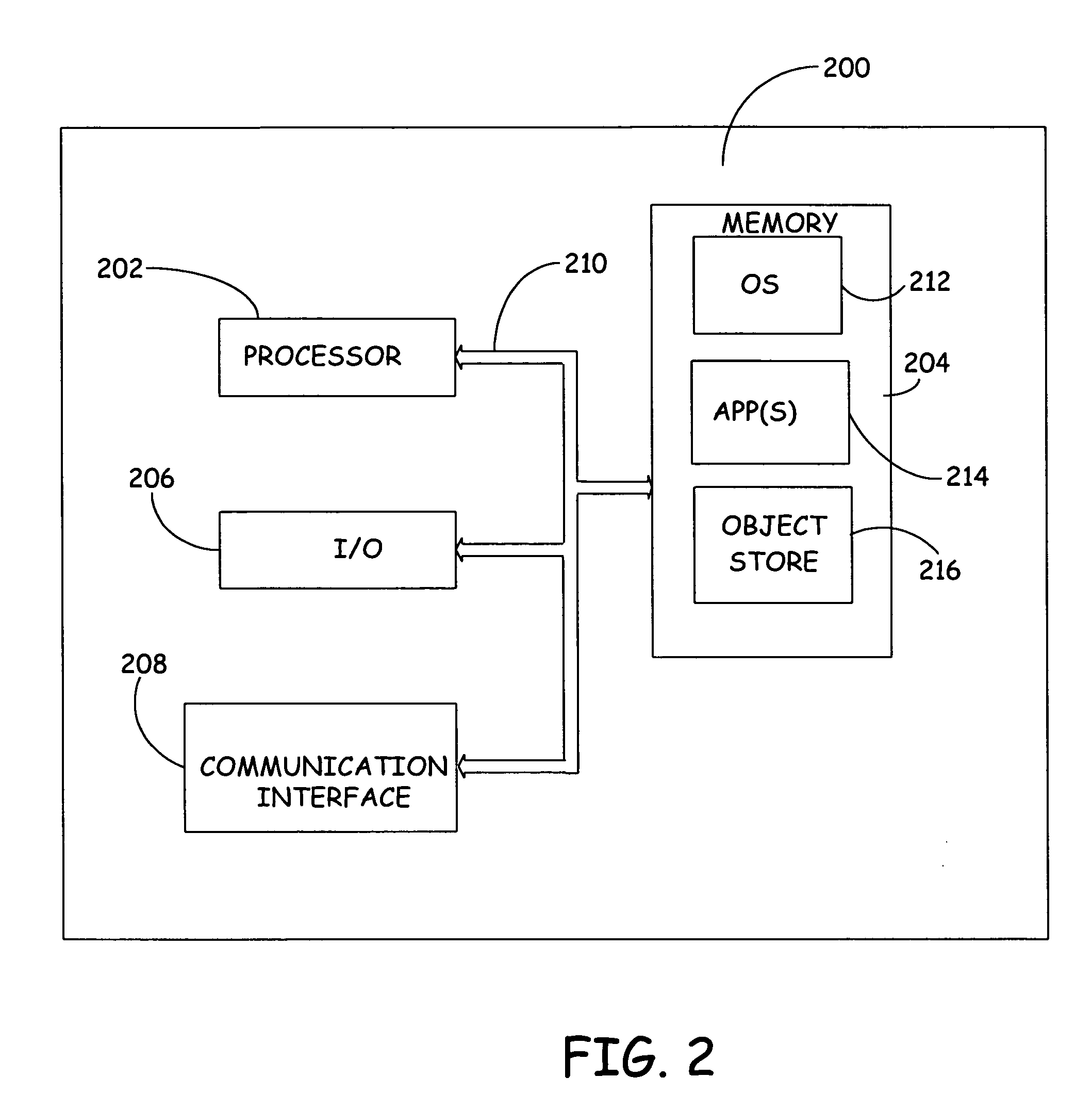
[0023]FIG. 1 illustrates an example of a suitable computing system environment 100 on which the invention may be implemented. FIG. 2 illustrates an example of a mobile device computing environment 200. The computing system environments 100 and 200 are only two examples of suitable computing environments, and are not intended to suggest any limitation as to the scope of use or functionality of the invention. Neither should the computing environments 100 and 200 be interpreted as having any dependency or requirement relating to any one or combination of components illustrated in the exemplary operating environment 100. Description of the methods and apparatus of the present invention with general reference to these computer architectures does not limit the invention to currently used computer architectures, but instead, the invention can be implemented on any suitable computer architecture, including future generations of computer architectures.

[0024] The invention is operational wit...


PUM


Abstract

A method, computer readable medium and system are provided which generate a model driven form user interface. In accordance with the method, a data model is mapped to a user interface model using at least one declarative map. The one or more declarative maps used to map the data model to the user interface model can be explicit maps which are external to a mapping engine used to generate the user interface model and any intermediate models.

Description

CROSS-REFERENCE TO RELATED APPLICATIONS [0001] Reference is hereby made to the following co-pending and commonly assigned patent applications filed on even date herewith: U.S. application Ser. No. ______ entitled “METHOD AND APPARATUS FOR GENERATING FORMS USING FORM TYPES” and U.S. application Ser. No. ______ entitled “METHOD AND APPARATUS FOR GENERATING USER INTERFACES BASED UPON AUTOMATION WITH FULL FLEXIBILITY”, both of which are incorporated by reference in their entirety.BACKGROUND OF THE INVENTION [0002] The present invention relates to the generation of forms. More particularly, the present invention relates to methods and apparatus for generating and updating form user interfaces (UIs). [0003] In typical business software products and applications, such as enterprise resource planning (ERP) products, a large number of forms or form user interfaces are used. It is not uncommon for the number of forms which are used in conjunction with a business software application to exceed...

Claims


Application Information

Patent Timeline
Patent Type & Authority Applications(United States)
IPC IPC(8): G06F9/44
CPCG06F9/451
Inventor BENDSEN, PERCHRISTENSEN, PETERVILLADSEN, PETER
Owner MICROSOFT TECH LICENSING LLC
Why Eureka
Try Eureka