
Installation for non-destructive inspection of a part

a technology for installing parts and parts, applied in the direction of instruments, structural/machine measurement, material magnetic variables, etc., can solve the problems of affecting the rotor, affecting the rotor, and affecting the rotor in particular its inside disk, etc., and achieving the effect of non-uniform regions and metal weakening zones

Active Publication Date: 2005-12-15
SN DETUDE & DE CONSTR DE MOTEURS DAVIATION S N E C M A
View PDF10 Cites 30 Cited by
  • Summary
  • Abstract
  • Description
  • Claims
  • Application Information

AI Technical Summary

Benefits of technology

[0007] Advantageously, said sensor support includes running wheels via which it remains in contact with said surface to be inspected throughout a scan. In this way, the optimum distance between the sensors and the material under inspection is maintained continuously.

Problems solved by technology

For example, such a rotor is made up of a plurality of spaced-apart titanium or nickel-based alloy disks that are welded together, and they therefore include annular cavities that have the reputation of being difficult to access.
Various kinds of defect or damage can affect the rotor, and in particular its inside disks.
Such non-uniform regions create zones of weakness in the metal.
It is also possible that cracks will appear, in particular after operating for a certain length of time.

Method used


Image

  • Installation for non-destructive inspection of a part
  • Installation for non-destructive inspection of a part
  • Installation for non-destructive inspection of a part

Examples


Embodiment Construction

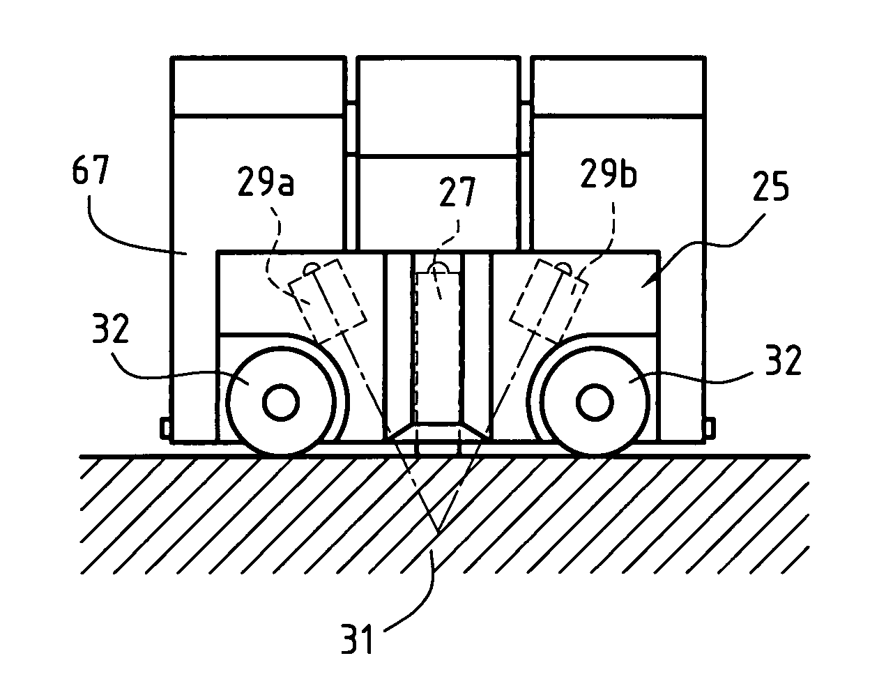
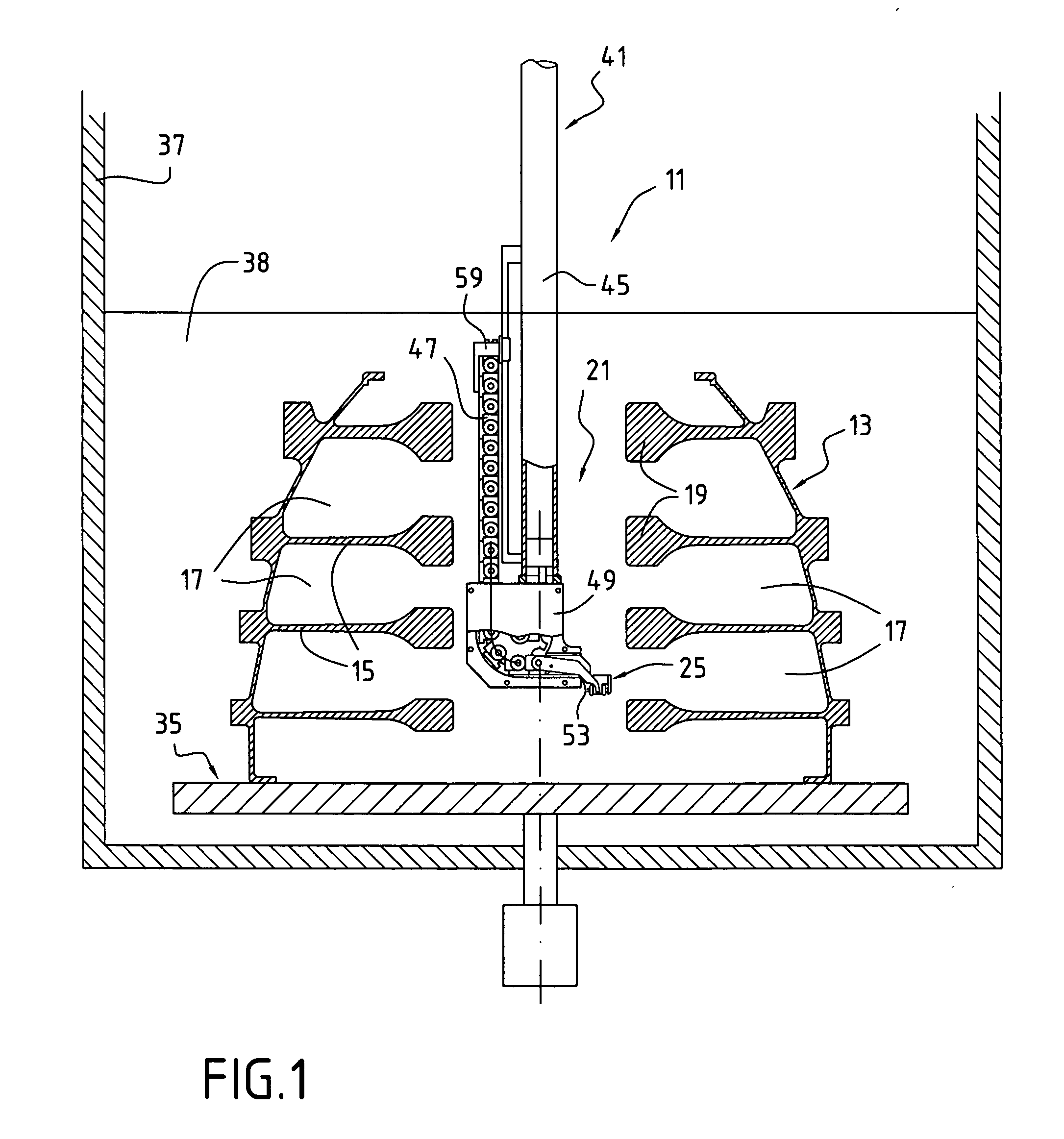
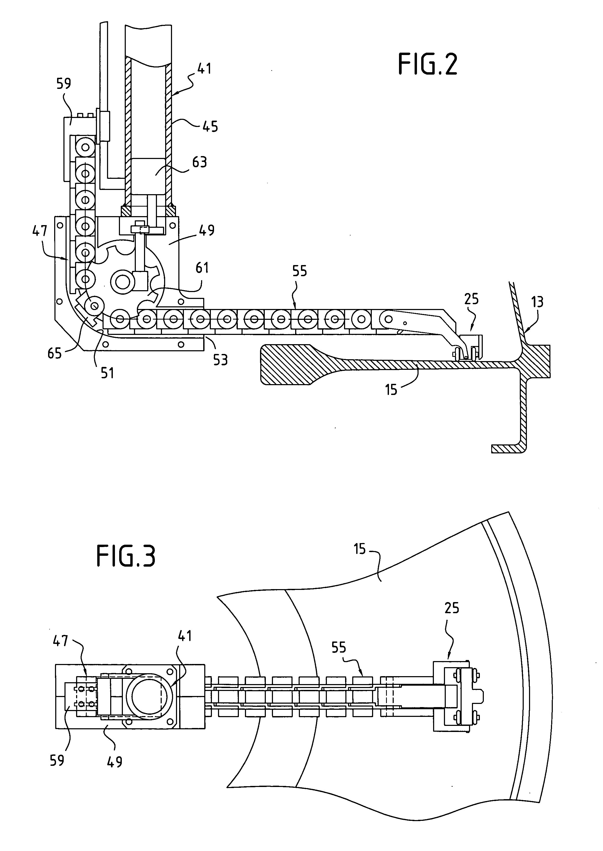
[0017] The installation 11 for non-destructive inspection as described herein and as shown in the drawings is more specifically adapted to inspecting a part 13 forming a rotor, of the type that is to be found in an airplane turbojet, where such a wheel is also referred to as a “spool”. In the jet, the part carries blades and it rotates at high speed. It is made entirely out of titanium alloy or nickel-based alloy, and it is built up from disks 15 that are welded to one another. Once it has been built, the part which is large (having a diameter of up to about 50 centimeters (cm)) is of a shape that is complex comprising a plurality of annular cavities 17 that are adjacent to one another on a common axis, being separated by annular disks 15, each presenting a thickening 19 close to its inside edge. A space 21 common to all of the cavities extends along the axis, and is thus located at the center of the part.

[0018] It is desirable specifically to inspect all of the disks 15 and more p...


PUM


Abstract

An installation for non-destructive inspection makes use simultaneously of sensors responsive to different physical characteristics. In an example, a sensor support, e.g. a kind of carriage having running wheels via which it comes into contact with the surface to be inspected, is fitted with two types of sensor, namely an eddy current sensor and at least one ultrasound sensor.

Description

[0001] The invention relates to an installation for non-destructive inspection of a part, and in particular a part of relatively large dimensions and complex shape, such as the rotor of a high pressure compressor, for example. The invention relates more particularly to an arrangement of sensors enabling a plurality of measurements to be performed simultaneously, thereby reducing the time required for acquiring the data needed to evaluate the state of the part. BACKGROUND OF THE INVENTION [0002] Certain parts of complex shape that are subjected to high levels of mechanical and thermal stress, such as a rotor of a high pressure compressor in a turbojet, for example, require rigorous inspection prior to being put into operation or during an overhaul. For example, such a rotor is made up of a plurality of spaced-apart titanium or nickel-based alloy disks that are welded together, and they therefore include annular cavities that have the reputation of being difficult to access. These cav...

Claims


Application Information

Patent Timeline
IPC IPC(8): G01N27/90G01M99/00G01N29/22G01N29/275
CPCG01N27/9013G01N29/22G01N29/275G01N2291/2693
Inventor CABANIS, PATRICKCOULETTE, RICHARDMARCEAU, CHRISTIAN
Owner SN DETUDE & DE CONSTR DE MOTEURS DAVIATION S N E C M A
Features
  • Generate Ideas
  • Intellectual Property
  • Life Sciences
  • Materials
  • Tech Scout
  • Unparalleled Data Quality
  • Higher Quality Content
  • 60% Fewer Hallucinations
Learn More