
Quick release shackle pin system

a shackle pin and quick release technology, applied in the direction of driving chains, couplings, rod connections, etc., can solve the problems of shackle and cross pins with mating slots and protrusions being particularly susceptible to dents and dings, and unsuitable for heavy loads

Inactive Publication Date: 2005-12-15
SILVA FRED
View PDF22 Cites 44 Cited by
  • Summary
  • Abstract
  • Description
  • Claims
  • Application Information

AI Technical Summary

Benefits of technology

[0042] The invention will be more fully understood by reference to the following drawings which are for illustrative purposes only:
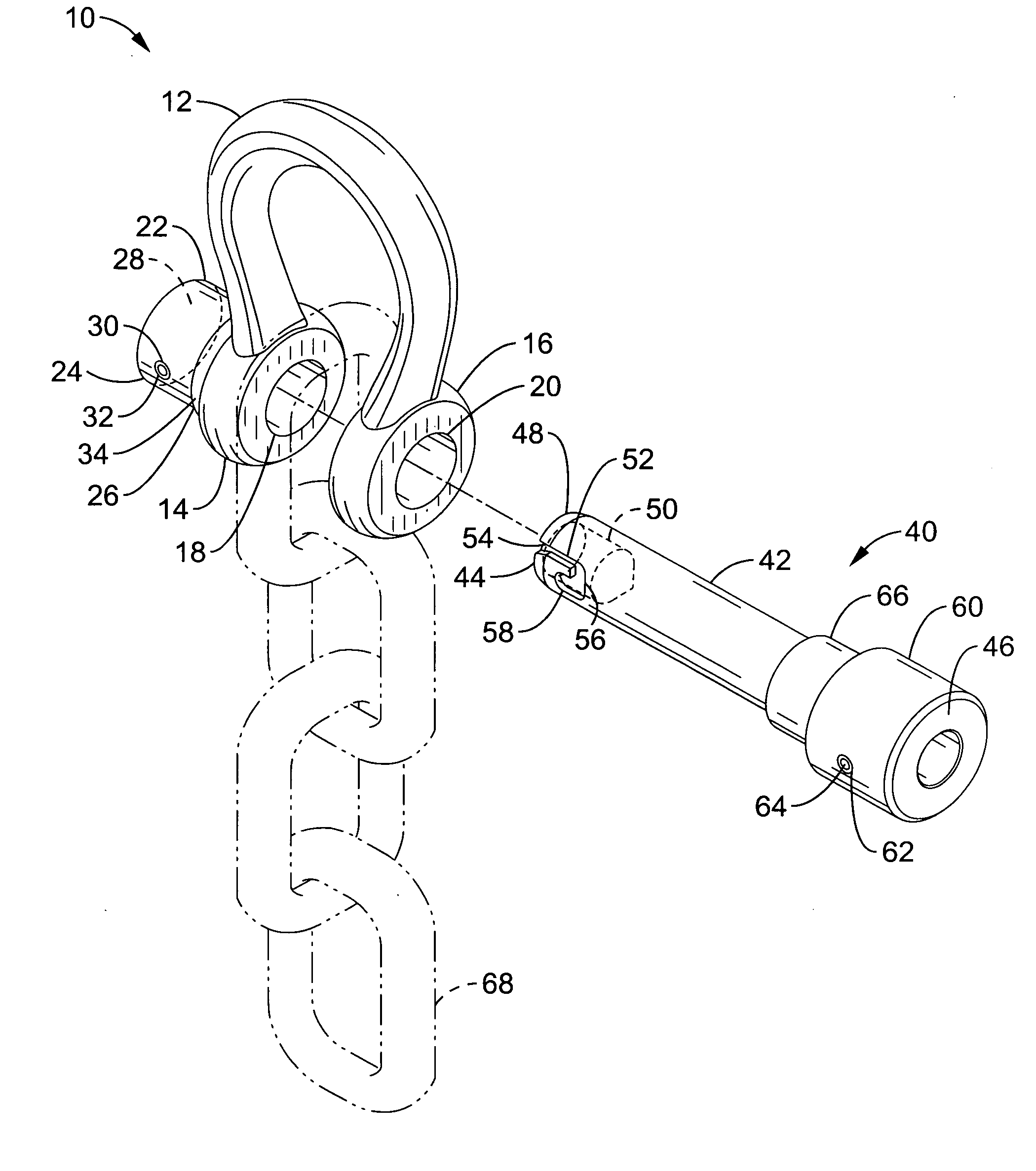
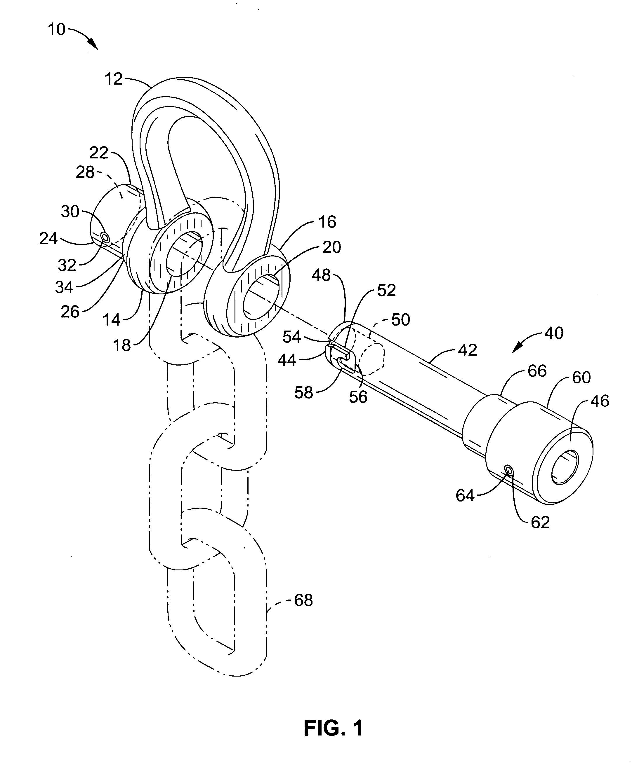
[0043]FIG. 1 is a perspective view of a quick release pin shackle system in an unsecured state.
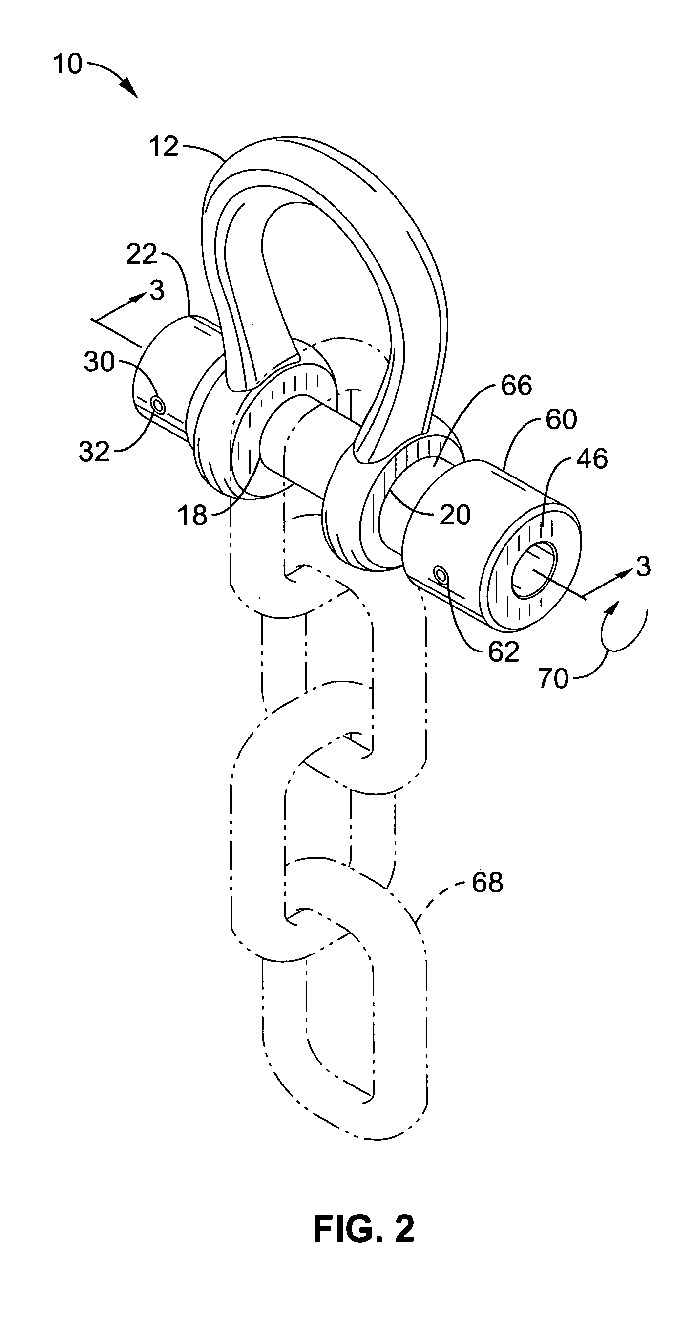
[0044]FIG. 2 is a perspective view of the quick release pin shackle system in FIG. 1 in a secured state.
[0045]FIG. 3 illustrates a cross section view of the quick release pin shackle system in ...

Problems solved by technology

For example, cross pins with central actuators also have a central bore that weakens the pin making them unsuitable for heavy loads.
Cross pins with threads, slots and protrusions are subject to jamming or damage when the shackle and pin are exposed to mud, sand, debris, etc.
Shackle and cross pins with mating slots and protrusions and threaded cross pins are particularly susceptible to dents, dings and strikes from hard objects that damage or deforms the threads, slot or protrusion.
Another problem with some existing shackles and cross pins is they require two hands to secure and unsecure.
This is not suitable for situations where the worker must support a chain or cable in the shackle with one hand and secure the shackle pin with the other.
Many of the complex solutions require several time consuming motions to secure and unsecure, or thread and unthread the cross pin.
Still others are not suitable for manipulation and engagement while wearing heavy construction or winter gloves.

Method used


Image

  • Quick release shackle pin system
  • Quick release shackle pin system
  • Quick release shackle pin system

Examples


Embodiment Construction

[0048] Referring more specifically to the drawings, for illustrative purposes the present invention is embodied in the apparatus generally shown in FIG. 1 through FIG. 5. It will be appreciated that the apparatus may vary as to configuration and as to details of the parts, and that the method may vary as to the specific steps and sequence, without departing from the basic concepts as disclosed herein. The present invention is described herein for use with a shackle or a clevis, however it is contemplated for use on yokes, forked rod ends, lifting lugs, pulley blocks, chain hoists or other lifting tools with aligned apertures. The invention may be used with other tools for lifting with a hook, cable loop, chain or rope. The invention is also contemplated in other applications that use a securing pin through aligned apertures such as guy wires, latches, doors, tailgates, hinged ramps, hitches, racks, tow bars, couplers, portable frames and portable support structures.

[0049]FIG. 1 ill...


PUM


Abstract

A spring loaded quick release pin and tubular receiver with a retainer pin configured to secure the quick release pin in a shackle, clevis, yoke or forked rod end. The receiver is welded to a shackle or cast with the shackle as a single body. One end of the quick release pin has aligned J slots that engage the retainer pin positioned in the receiver with a clockwise twist. The other end of the quick release pin has a cap and a spring loaded sleeve that biases the cross pin against outside of the second leg of the shackle. The spring bias keeps the short leg of the J slot engaged with the retaining pin. The quick release pin is removed with a push and counter clockwise twist. The invention includes a kit with a receiver, a bushing and a quick release pin for installing or retrofitting existing shackles.

Description

CROSS-REFERENCE TO RELATED APPLICATIONS [0001] This application claims priority from U.S. provisional application Ser. No. 60 / 578,714 filed on Jun. 9, 2004 and is incorporated herein in its entirety.STATEMENT REGARDING FEDERALLY SPONSORED RESEARCH OR DEVELOPMENT [0002] Not Applicable INCORPORATION-BY-REFERENCE OF MATERIAL SUBMITTED ON A COMPACT DISC [0003] Not Applicable NOTICE OF MATERIAL SUBJECT TO COPYRIGHT PROTECTION [0004] A portion of the material in this patent document is subject to copyright protection under the copyright laws of the United States and of other countries. The owner of the copyright rights has no objection to the facsimile reproduction by anyone of the patent document or the patent disclosure, as it appears in the United States Patent and Trademark Office publicly available file or records, but otherwise reserves all copyright rights whatsoever. The copyright owner does not hereby waive any of its rights to have this patent document maintained in secrecy, inc...

Claims


Application Information

Patent Timeline
IPC IPC(8): E05B65/48F16G15/06
CPCF16G15/06Y10T403/7007Y10T403/599Y10T403/32893
Inventor SILVA, FRED
Owner SILVA FRED
Learn More