

Medical device guiding system
a technology of guiding system and medical device, which is applied in the direction of medical devices, other medical devices, catheters, etc., can solve the problems of too large and rigid for many procedures, devices that often fail to reach a target location, and devices that often don't produce sufficient turning radius, etc., and achieve the effect of increasing the stiffness of the sha
- Summary
- Abstract
- Description
- Claims
- Application Information
AI Technical Summary
Benefits of technology
Problems solved by technology
Method used
Image

Examples
Embodiment Construction
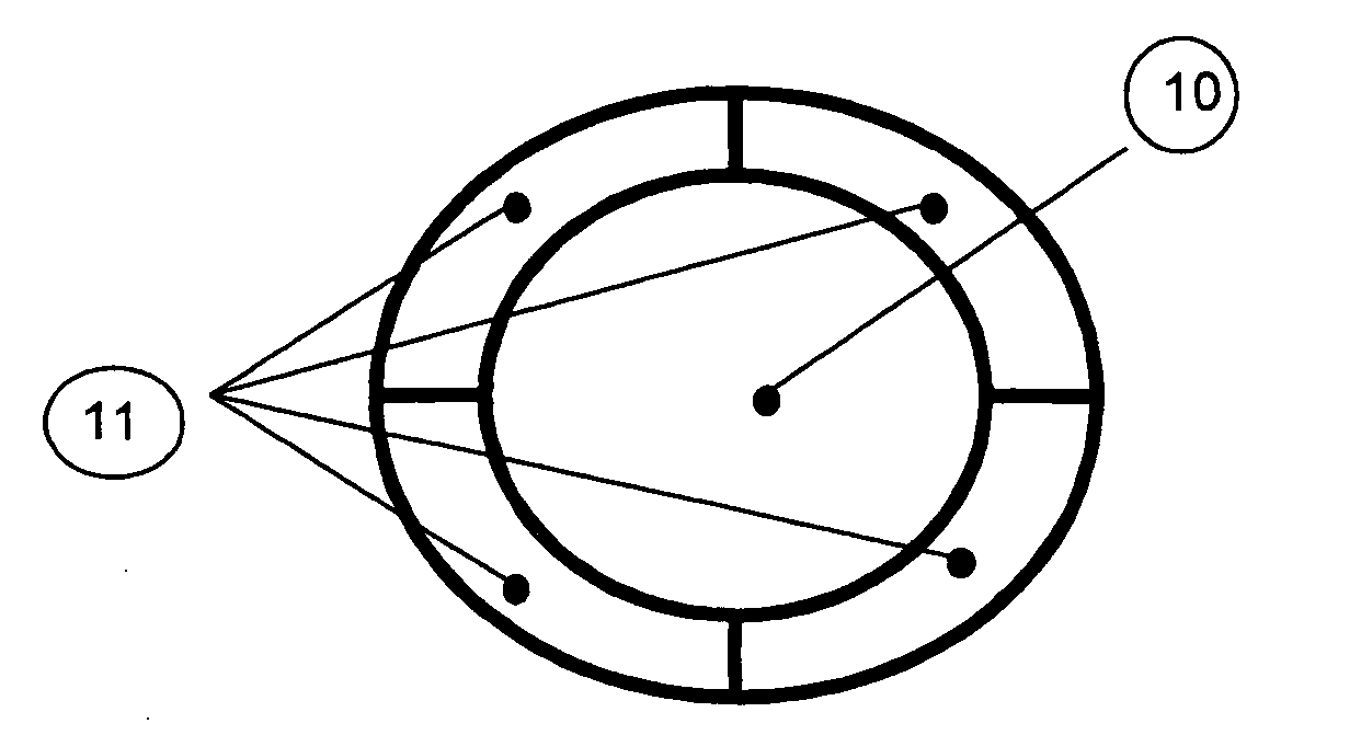
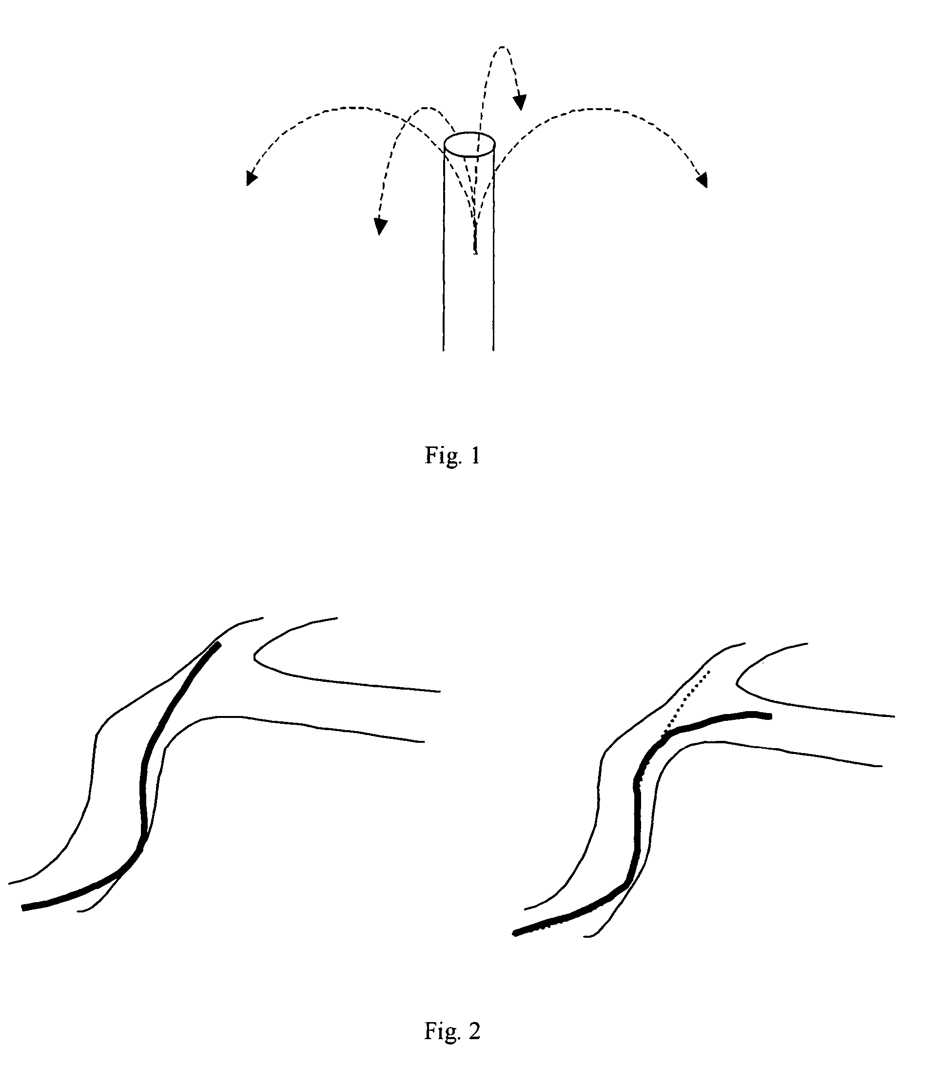
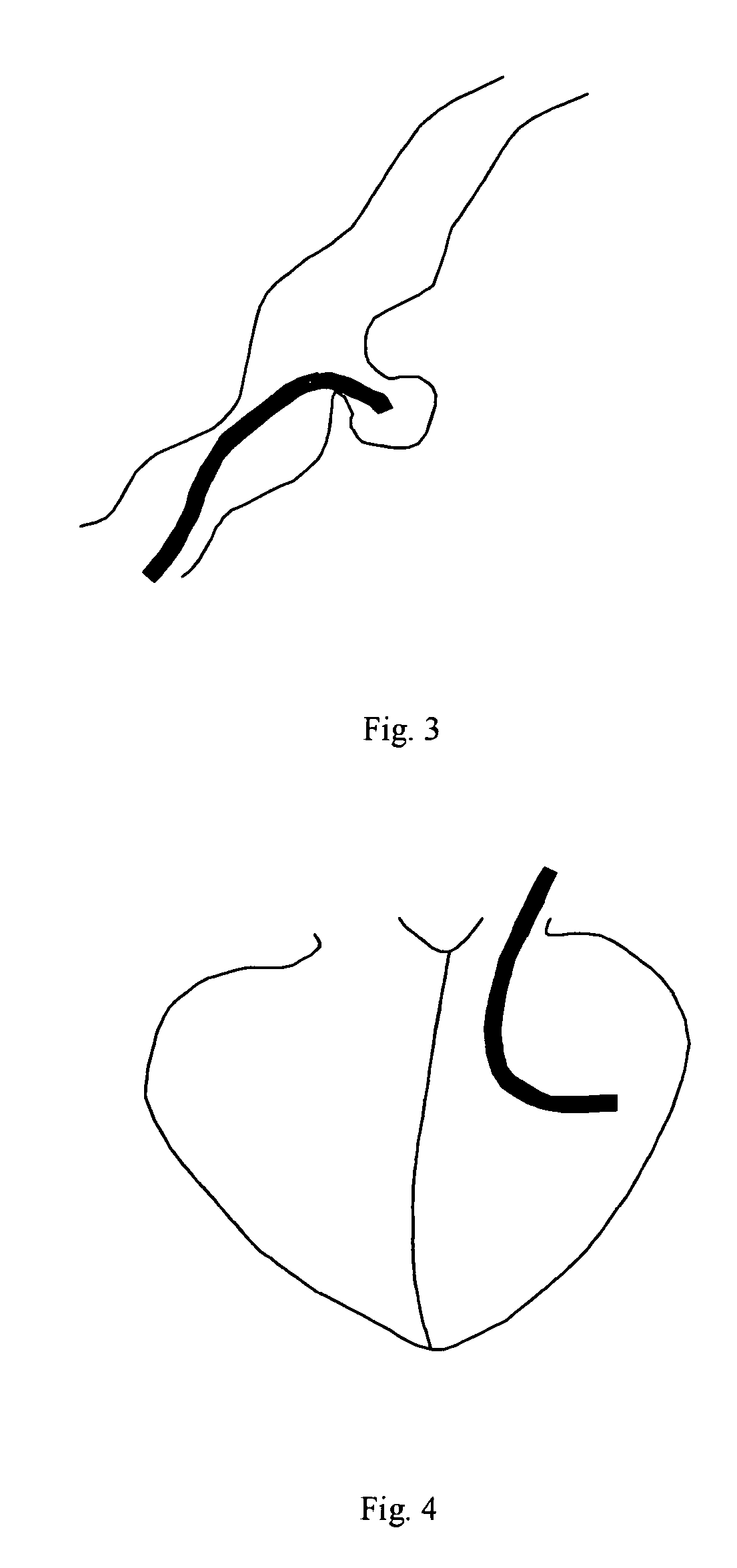
[0021] The invention disclosed herein is intended to provide physicians with a tool to allow better treatment options for patients with disease to the heart, brain and peripheral vascular system. It may be added to the external surface of a catheter, guidewire or obturator. The system can be manufactured as part of the catheter, guidewire or obturator device or attached to the device in the catheterization lab. Pressurizing the inflation lumens causes the distal end of the device to curve in different directions as shown in FIG. 1. The amount of curvature increases with increased pressure until maximum curvature is reached. Maximum deflection will be at least 45°. This will help a physician perform the procedure in several ways, including navigate through highly curved vessels as shown in FIG. 2, or point the tip towards the intended target such as in a aneurysm as shown in FIG. 3 or heart chamber wall as shown in FIG. 4. Below is described the preferred embodiments of this guiding ...
PUM
 Abstract
Description
Claims
Application Information