Pen needle and safety system

a safety system and needle technology, applied in the field of safety shield systems, can solve the problems of inability to adapt the safety shield system to use with pen injectors, inconvenient operation, and difficulty in manipulating the hypodermic needle necessary to carry out injections, so as to eliminate the rotational movement of the shield or a complex track system, the effect of reducing the risk of infection

Inactive Publication Date: 2005-12-15
BECTON DICKINSON & CO
View PDF99 Cites 61 Cited by
  • Summary
  • Abstract
  • Description
  • Claims
  • Application Information

AI Technical Summary

Benefits of technology

[0006] The safety shield system of the present invention solves the above-described shortcomings of the prior art by providing a needle assembly having a shield that is movable from a first position, in which it encloses and covers the tip of the second or patient end of a double-ended needle cannula, to a second position, in which the tip of the second end of the needle cannula is exposed, to a third position, in which the shield lockingly encloses and covers the tip of the second end of the needle cannula. In addition, the present invention provides a cap that lockingly covers the first end of the needle cannula. Thus, the present invention provides means for lockably shielding both ends of a double-ended needle cannula. The present invention also prevents retraction of the shield during assembly of the needle assembly on the pen injector.
[0011] The safety shield system in accordance with the present invention thus provides reliable operation and protection from the needle cannula after use of the needle assembly. In certain implementations, the generally tubular safety shield moves axially guided by the axially extending channel-shaped tracks as described herein, thereby eliminating rotational movement of the shield or a complex track system. The tubular body portion of the clip member includes a plurality of spaced axially extending radially projecting ribs which are received in axially extending grooves in the tubular portions of the shield, assuring axial movement of the shield during retraction and extension of the shield as described herein. The resilient fingers of the clip member include a U-shaped portion integrally connected to the tubular portion of the clip member and hook-shaped free end portions as described herein. This configuration provides additional resiliency for the hook-shaped end portions of the fingers. Further, the U-shaped portion of the fingers preferably open toward the generally closed end of the shield and the spring includes a first end received in the U-shaped portions of the fingers and a second end biased against the generally closed end of the shield assuring reliable movement of the shield.
[0012] The safety shield system of this invention also prevents retraction of the shield during assembly of the needle assembly on the pen injector. As set forth above, one problem with certain pen needles has been potential piercing of the cap during threaded assembly of the cap and shield assembly on the pen injector thereby exposing the user to puncture. The cap of the improved safety shield system includes a plurality of radially inwardly projecting ribs which are received in the axially extending grooves in the tubular portion of the shield against the axially projecting ribs on the clip member. The grooves in the tubular portion of the shield preferably extend through the sidewall of the shield from adjacent the generally closed end to the ribs. These internal ribs on the cap prevent retraction of the shield while the shield is held within the cap and during threaded assembly of the cap and shield assembly on the pen injector, thereby preventing accidental puncture during assembly.

Problems solved by technology

The manipulation of a hypodermic syringe necessary to carry-out an injection may be difficult and inconvenient, particularly where the injection is self-administered.
Thus, such safety shield systems are not adaptable for use with pen injectors, which are intended for multiple uses.

Method used


Image

  • Pen needle and safety system
  • Pen needle and safety system
  • Pen needle and safety system

Examples


Embodiment Construction

[0029] As set forth above, the improved safety shield system is particularly but not exclusively adapted for use with a pen injector. As will be understood, however, the safety shield system of this invention may also be used with other injection devices, including, by way of illustration and not limitation, hypodermic syringes and other known or hereafter developed drug delivery devices.

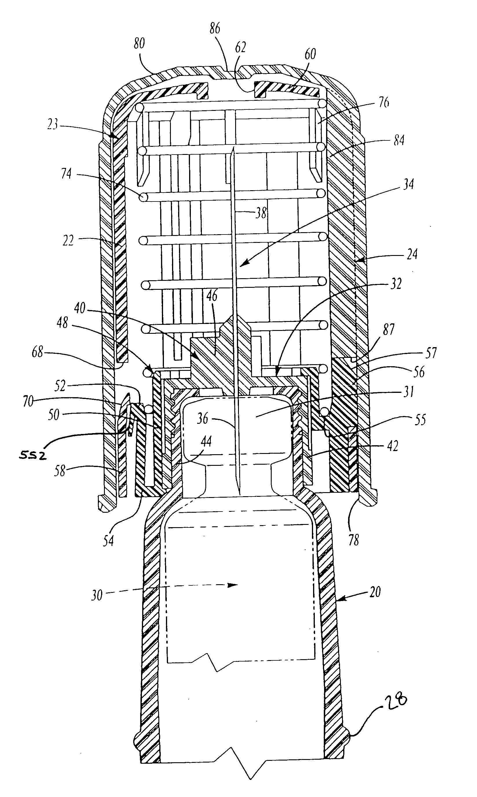
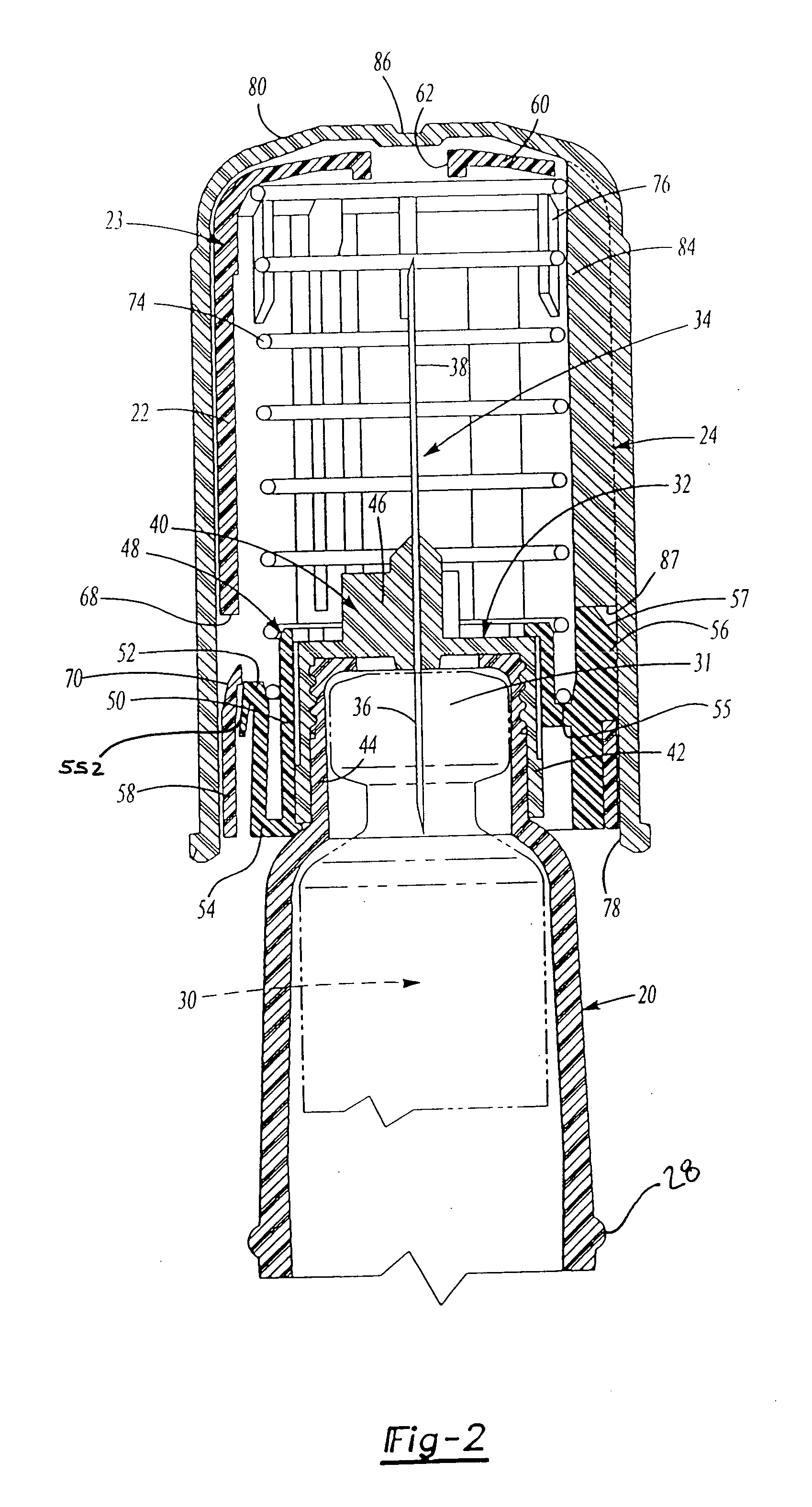
[0030] The needle assembly 23 of the present invention may be removably provided on a pen injector 20. The pen injector depicted in FIG. 1 includes an open end 26 which may include external ribs 28 to facilitate gripping of the pen injector 20 by the user during attachment of the needle assembly 23 to the pen injector 20. As shown in FIG. 2, the pen injector 20 is sized and shaped to receive a vial 30 (shown in phantom) having a pierceable closure such as a rubber septum (not shown) in an open tubular end portion 31 of the vial.

[0031] With reference first to FIG. 1, the inventive safety shield sys...


PUM


Abstract

A safety shield system having a needle assembly with a safety shield movable from a first position enclosing an end of a needle cannula, to a second position exposing the end of the needle cannula for injection, to a third position lockingly enclosing the end of a needle cannula. The safety shield system permits retraction of the safety shield during use, but extends the shield enclosing the needle cannula in a locked position following use. The safety shield system also has a cap for receiving the needle assembly and lockingly enclosing another end of the needle cannula. Thus, both ends of a double-ended needle cannula are lockingly enclosed following use of the needle assembly of the inventive safety shield system.

Description

CROSS-REFERENCE TO RELATED APPLICATIONS [0001] This patent application is a continuation of U.S. patent application Ser. No. 10 / 191,714, which is a continuation-in-part of U.S. patent application Ser. No. 10 / 072,691, which claims priority to U.S. Provisional Application Ser. No. 60 / 222,454. FIELD OF THE INVENTION [0002] The present invention is a safety shield system for an injection device comprising a needle assembly and cap which provide for protection of both ends of a double-ended needle cannula after injection using the needle assembly and injection device. As used herein, the term injection device refers to any device which may contain a medicament, in whatever form (e.g., liquid, solid, powder, or combinations thereof), and which may be used to inject such medicament into a patient. As used herein, the term injection device includes sterilized and non-sterilized devices, filled (with medicament) and unfilled devices, and any variation or combination thereof. For example, an ...

Claims


Application Information

Patent Timeline
Patent Type & Authority Applications(United States)
IPC IPC(8): A61M5/00A61M5/24A61M5/31A61M5/32A61M5/34A61M5/50
CPCA61M5/002A61M5/24A61M5/3202A61M5/3205A61M5/326A61M2005/3267A61M5/347A61M5/5086A61M2005/3104A61M2005/3215A61M2005/3247A61M5/3271
Inventor GIAMBATTISTA, LUCIOSALVO, DAVID DE
Owner BECTON DICKINSON & CO
Why Eureka
Try Eureka