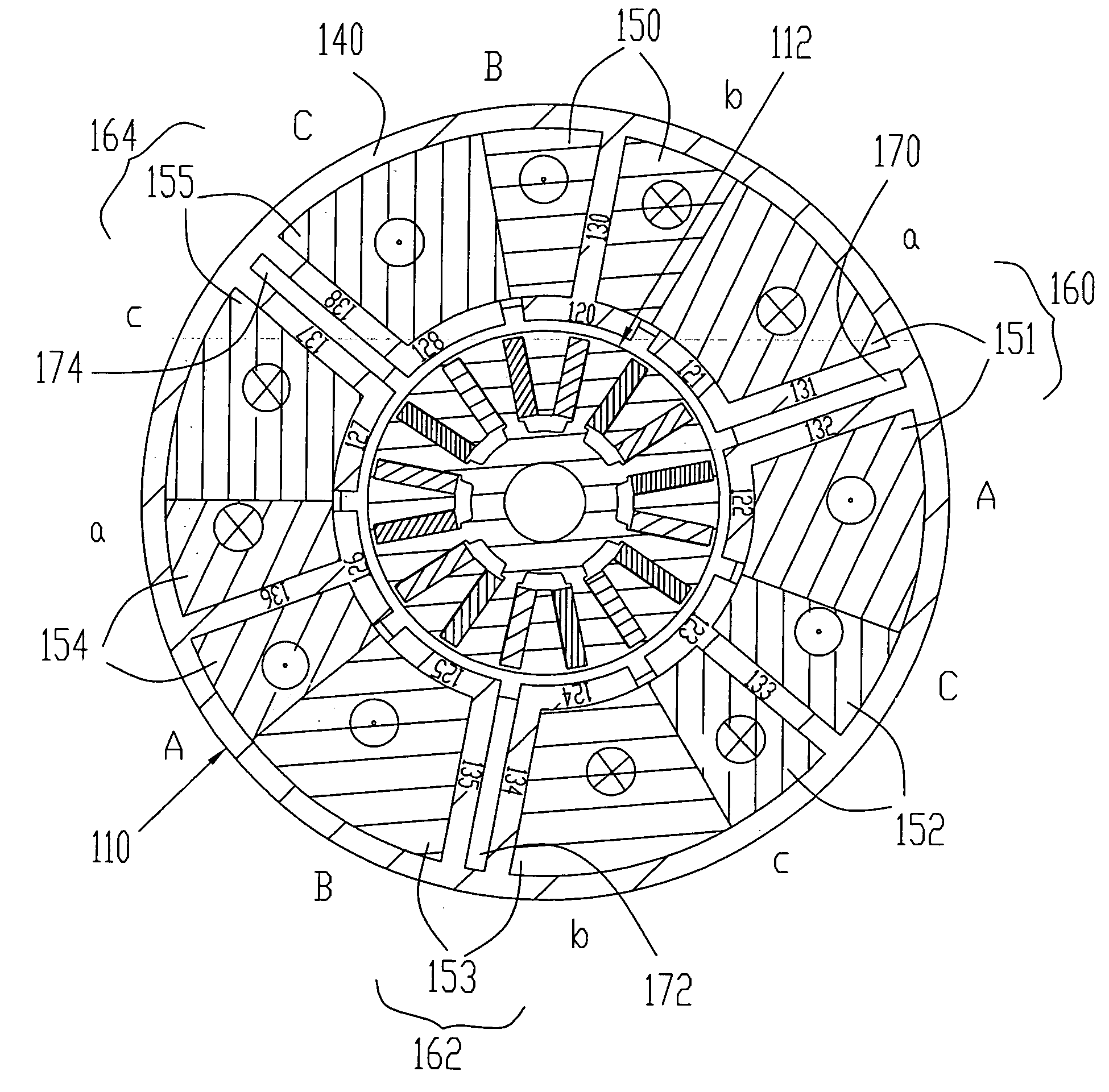
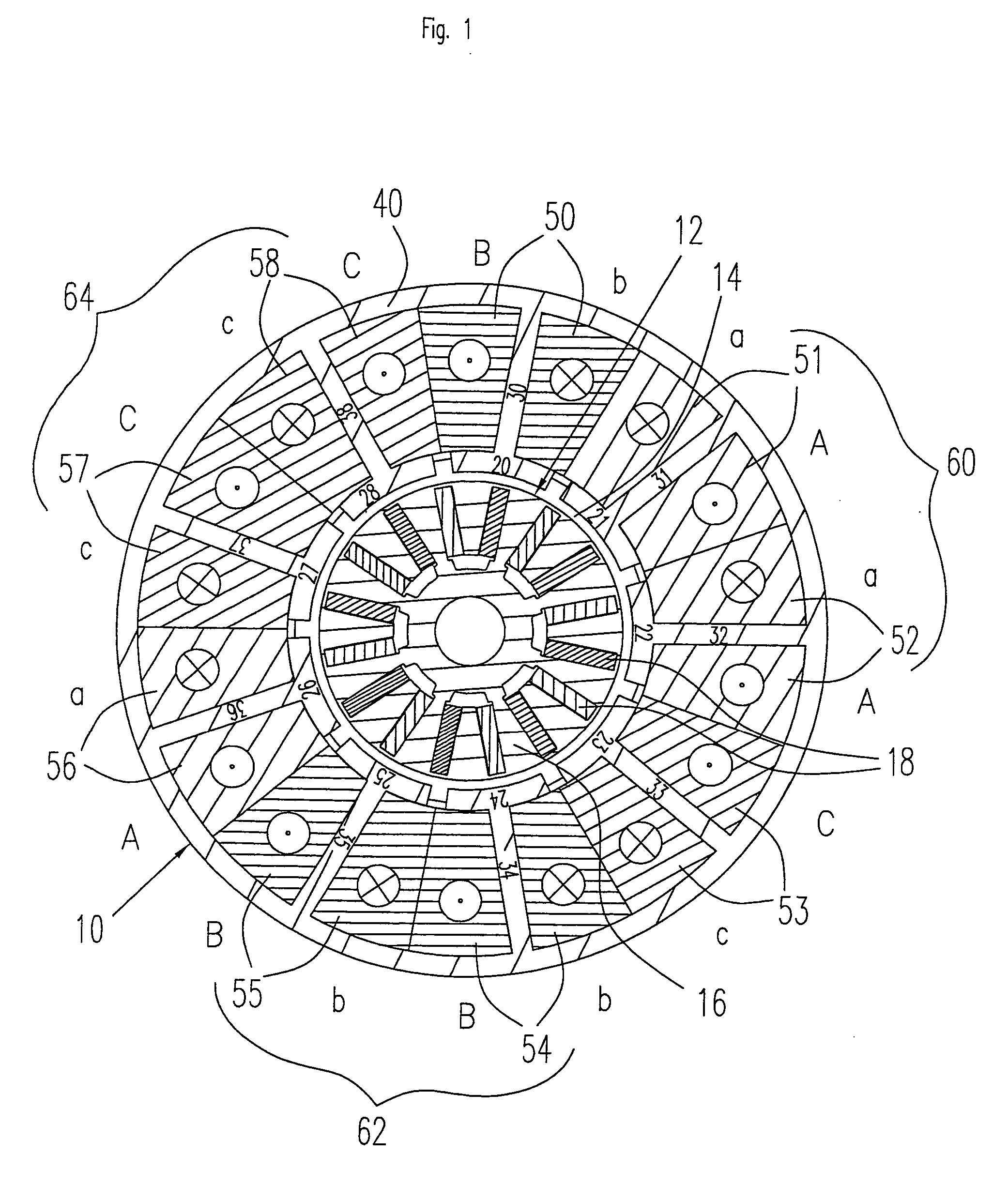
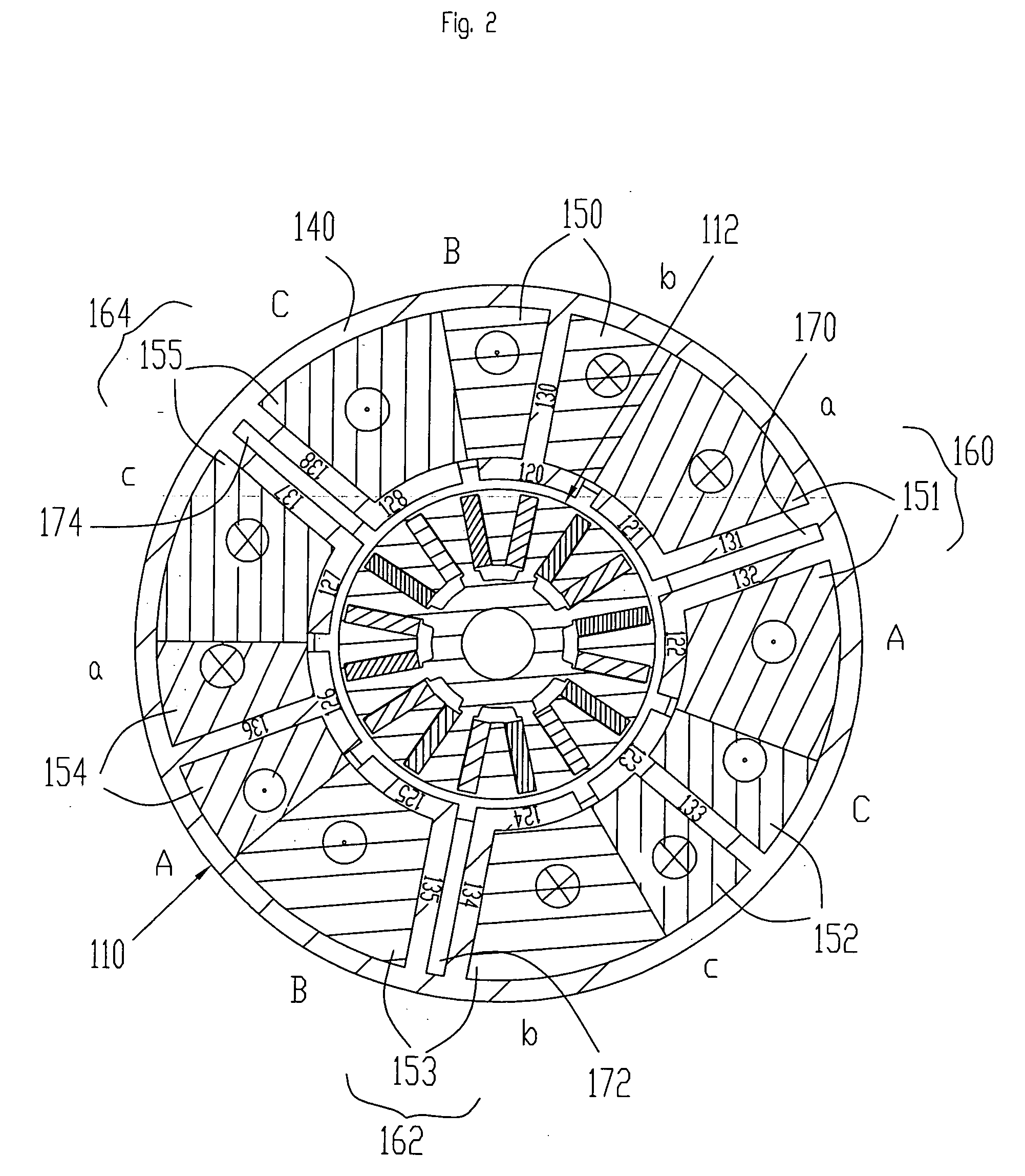
[0007] The invention is based on the realization that the winding spaces, which in known motors contain opposed windings of the same phase and thus do not contribute to the build up of torque, can be reduced in order to create space for windings which make a contribution to the build up of torque. To this effect, the pole bridges for each stator pole group are moved closer together, whereby the minimum spacing of these pole bridges should correspond approximately to the width of the associated pole gaps. The small winding space thus formed may remain empty while the adjoining stator pole slots are enlarged and can accordingly accommodate more winding wire. Irrespective of the combination of the number of rotor poles and the number of stator slots, the motor according to the invention thus does not have any adjoining opposed windings of the same phase that do not contribute to the build up of torque. In fact, these winding sections are eliminated and the stator slot provided between the two
stator poles of a stator pole group for this purpose in the prior art is reduced as far as possible, i.e. the pole bridges of the stator poles concerned are preferably moved closer together to the width of a stator pole gap, making considerably more winding space available for the other windings. Thus for the same combinations of the number of rotor poles and the number of stator slots, a significant improvement in the efficiency of the motor can be achieved.
[0008] In one embodiment, one or two stator pole groups are provided for each phase, each stator pole group being formed from two stator poles. In this way the stator pole groups, in whose intervening spaces no winding sections are provided, are distributed evenly over the stator, enabling a symmetric construction to be achieved and consequently a simple and low-cost manufacturing process to be realized.
[0010] The spacing between two pole bridges of a stator pole group, in whose intervening space no winding sections have been provided, preferably corresponds to the width of the stator pole gap between two adjoining pole heads. On the one hand, this arrangement allows unused winding space to be reduce to a minimum and, on the other hand, provides a
DC motor in which the numbers of rotor poles and stator slots as well as the relative position of the rotor poles to the stator pole heads remain unchanged compared to motors of the prior art. At a higher output, this kind of motor can achieve the same operating performance in terms of
torque ripple and
cogging torque as a known motor having a corresponding combination of pole / slot numbers.
[0011] In an embodiment, the product of the number of stator poles and the number of rotor poles is the smallest number which can be divided in whole numbers by both the number of stator poles as well as by the number of rotor poles. In this embodiment, the respective angular offsets of each rotor pole differ from each other with respect to the corresponding opposing pole heads. As a result, the number of cogging cycles is maximized. An even distribution of
cogging torque and thus a minimization of cogging torque is achieved. For example, in the case of a motor having nine slots and 16 poles, there is very low cogging torque at 144 cogging torque cycles per rotation. (144 is the smallest number that can be divided by both 9 and 16.) The higher the number of cycles, the lower is the cogging torque. This then goes to produce a very smooth running performance with low cogging torque and low
torque ripple or fluctuations in the driving torque.
[0012] In another embodiment, at least one stator pole is disposed between two adjoining stator pole groups, the phase of the stator pole differing from the phases of the adjoining stator poles. This goes to ensure that stator pole groups whose pole bridges are disposed with only a small spacing between them are separated by an “unchanged” stator pole, thus simplifying the construction.
[0013] The motor preferably has nine stator slots and two rotor poles, nine slots and 16 rotor poles, 15 slots and four rotor poles or 18 slots and four rotor poles. DC motors having these combinations of the number of poles and the number of slots produce winding patterns in which two opposed windings of the same phase are located side by side in a stator slot, so that the winding sections in this stator slot do not contribute to the build up of torque. The respective winding sections can thus be eliminated and, according to the invention, the corresponding winding spaces can be reduced to the width of a stator pole gap, allowing the remaining stator pole slots to be increased as winding spaces.

