Fabricated air core reactor

a technology of air core reactor and air core, which is applied in the direction of transformer/inductance details, fixed inductances without magnetic cores, and inductances with fixed inductances, etc., can solve the problems of iron core reactors that can also add considerable weight to the product, reduce the efficiency of power converters, and assimilate watt loss of the system

Inactive Publication Date: 2005-12-22
GENERAL ELECTRIC CO
View PDF2 Cites 4 Cited by
  • Summary
  • Abstract
  • Description
  • Claims
  • Application Information

AI Technical Summary

Benefits of technology

[0010] Thus, there exists a need in the art for a fabricated air core reactor that

Problems solved by technology

A disadvantage of the resistors is the IR across them, thereby resulting in an associated watts loss for the system.
Thus, the efficiency of the power converter is reduced.
The iron core reactors can also add considerable weight to the product.
The complexity and costs of designing, installing, maintaining, and servicing such a computer controlled active controlled system can be quite high.
A disadvantage or shortcoming of the bo

Method used


Image

  • Fabricated air core reactor
  • Fabricated air core reactor
  • Fabricated air core reactor

Examples


Embodiment Construction

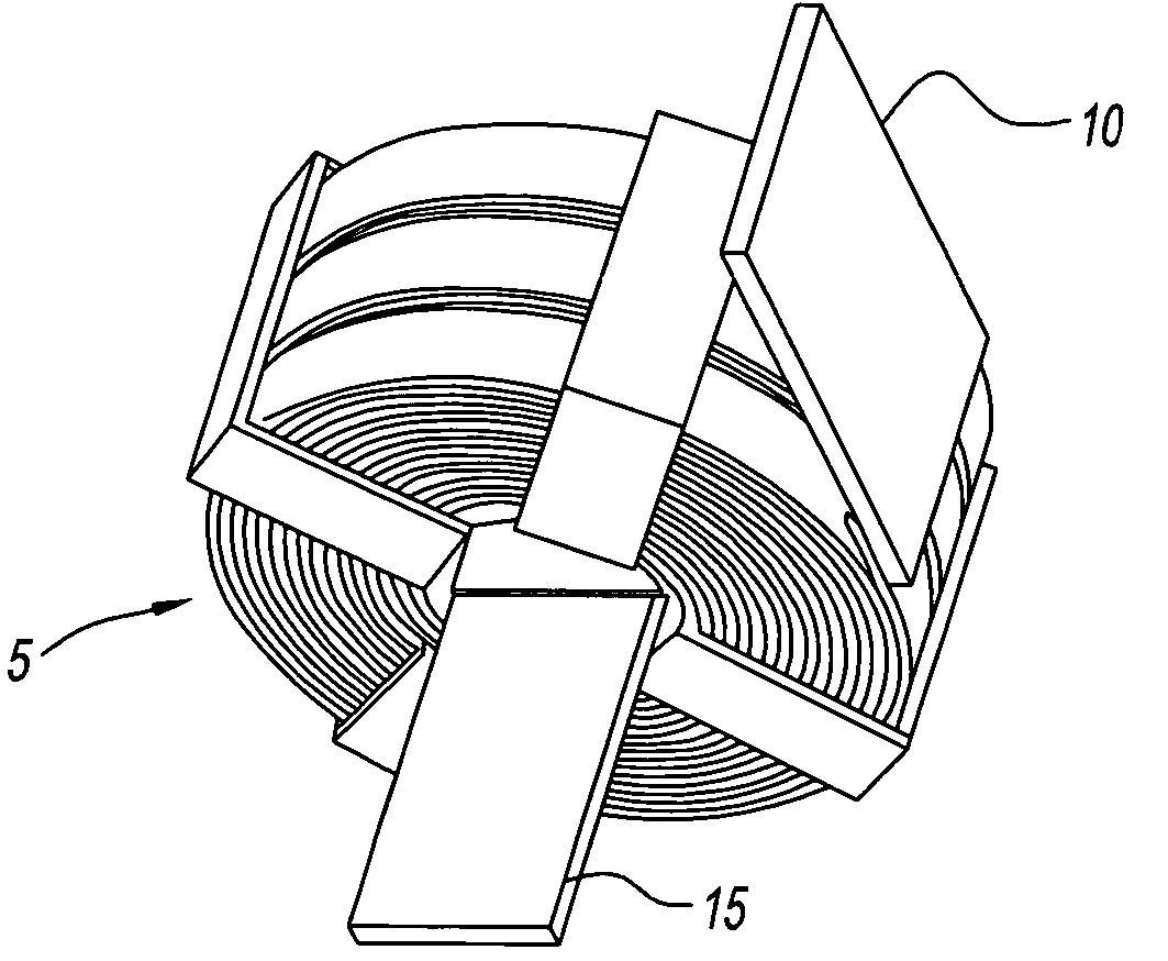
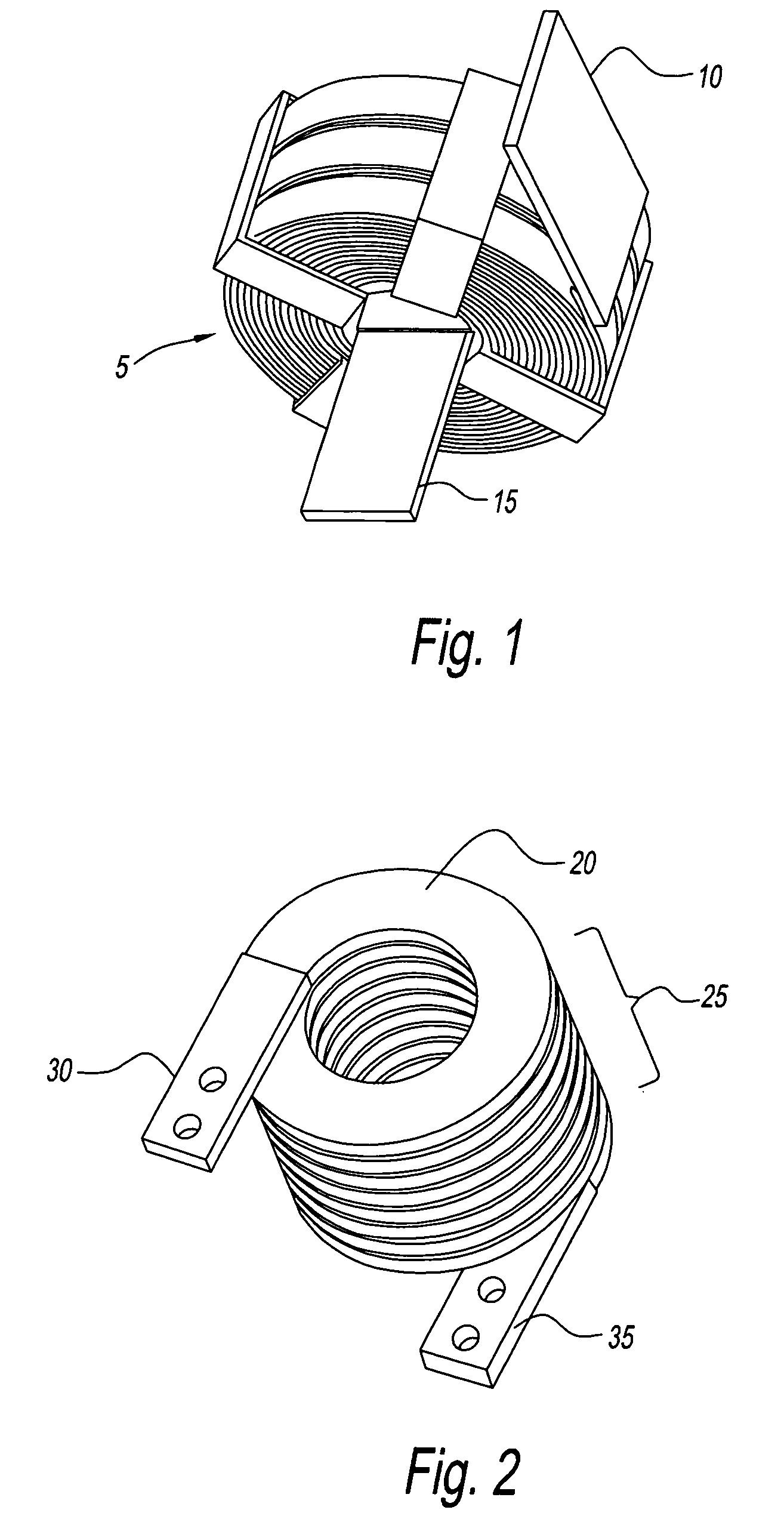
[0017] Prior air core reactors have been manufactured using a number of techniques. In general, prior air core reactor designs have included roll formed reactors and edge wound reactors such as a roll formed reactor shown in FIG. 1 and an edge wound reactor as shown in FIG. 2, respectively. Such reactors are generally made of aluminum or copper, and include a variety of insulation and bracing designs.

[0018] The roll formed reactor of FIG. 1 includes a number of generally flat, roll formed conductors coaxially arranged. The roll formed reactor has terminals 10 and 15 electrically connected to roll formed conductors 5.

[0019] The edge wound reactor of FIG. 2 has a generally flat, edge wound conductor 20 configured as coaxial spiral windings 25. The edge wound reactor has terminals 30 and 35 electrically connected to edge wound conductor 20.

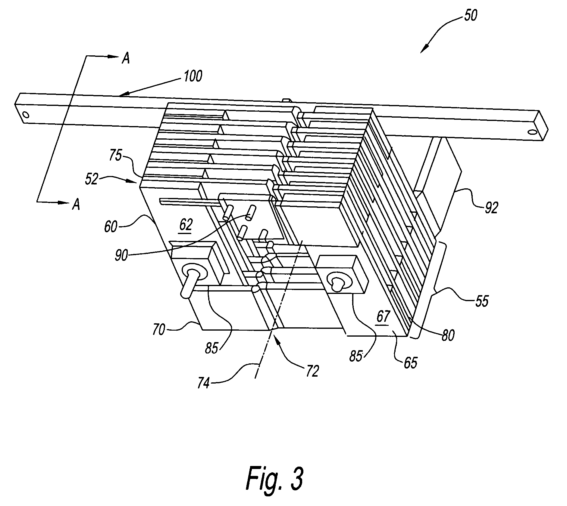
[0020] With reference to FIGS. 3 and 4, there is shown a fabricated air core reactor generally represented by reference numeral 50. Air core reac...


PUM


Abstract

A method and apparatus for an air core reactor including a plurality of straight members and a plurality of offset members, the plurality of straight and offset members are interconnected to form an orthogonal spiral having an air core therethrough.

Description

BACKGROUND OF INVENTION [0001] 1. Field of the Invention [0002] The present disclosure relates to electrical reactors. More particularly, the present disclosure relates to a method and system of a fabricated air core reactor for use in electrical power distribution systems. [0003] 2. Description of the Related Art [0004] Air core reactors or power reactors are known in the art. In an air core reactor, the magnetic flux travels in air, maintaining inductance with all currents. Air core reactors are used in electrical power distribution systems for a variety of purposes such as, for example, current limiting reactors, filter reactors, ripple reactors, and shunt reactors. [0005] In power distribution systems having parallel power converters, it is desired that the current between the converters is balanced. It is desired that the currents on each line feeding the converters, including transient and fault currents, are controlled so that other components such as expensive solid state de...

Claims


Application Information

Patent Timeline
IPC IPC(8): H01F17/02H01F27/24H01F27/28H01F37/00
CPCH01F17/02H01F37/005H01F27/2847
Inventor EDMUNDS, HOWARD ROSSALKEN, BRIAN MATTHEWPHILLIP, ANDREWMCMENAMIN, CHRISTOPHERMOORE, CHRISTOPHER T.BITTNER, JOHN EARLNASH, STEPHEN DANIELMILLER, MICHAEL L.
Owner GENERAL ELECTRIC CO
Why Eureka
Try Eureka