
Method and apparatus to simulate an outdoor window for panorama viewing from a room

a technology of panorama viewing and simulation images, applied in the field of simulation images of outdoor windows, can solve the problems of inability to replace to a new one, extra cost of simulation images already exists, and the windowless room has a computer

Inactive Publication Date: 2005-12-22
JONG CHIOU MUH
View PDF5 Cites 35 Cited by
  • Summary
  • Abstract
  • Description
  • Claims
  • Application Information

AI Technical Summary

Benefits of technology

"The patent describes a method and system for simulating windows to show panorama views from multiple locations. Users can see the outdoor scene from their favorite locations in a room with simulated window coverings, and can manipulate them to their desired openings and positions. The system also includes background sound from the scene location. This technology can be useful for hotels or private condos with expensive views, and can also be used as a decoration item."

Problems solved by technology

However, there will be no plurality of types and styles of the curtains in such arrangement and sometimes it is not easy to install particular style of curtains, blinds or the shades, and once installed, it is difficult to replace to another one.
Therefore, an extra cost already exists by using computer to process the simulation images.
First, not every windowless room has a computer.
Personal computers usually take more than 30 seconds to boot up.
It would be too tedious if one needs to start a computer before starting the window simulation every time unless the computer stays in running mode all day long.
Third, using computer keyboard / mouse to move curtain up and down does not offer as good in simulation fidelity as using the user interface devices installed directly around the rim of the display screen.

Method used


Image

  • Method and apparatus to simulate an outdoor window for panorama viewing from a room
  • Method and apparatus to simulate an outdoor window for panorama viewing from a room
  • Method and apparatus to simulate an outdoor window for panorama viewing from a room

Examples


Embodiment Construction

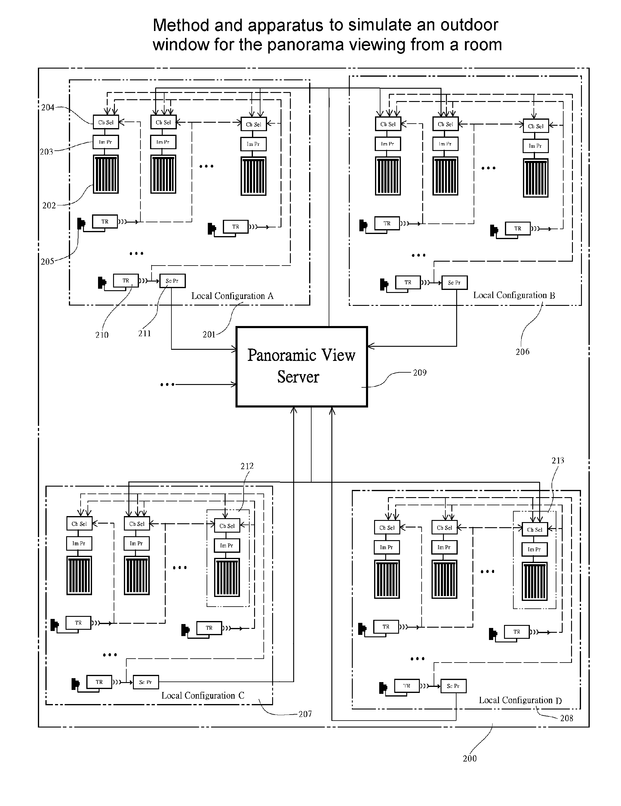
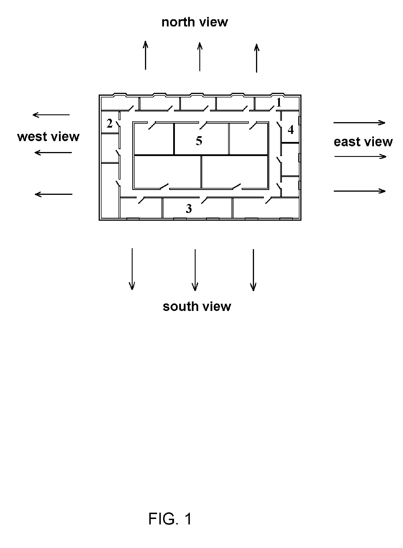
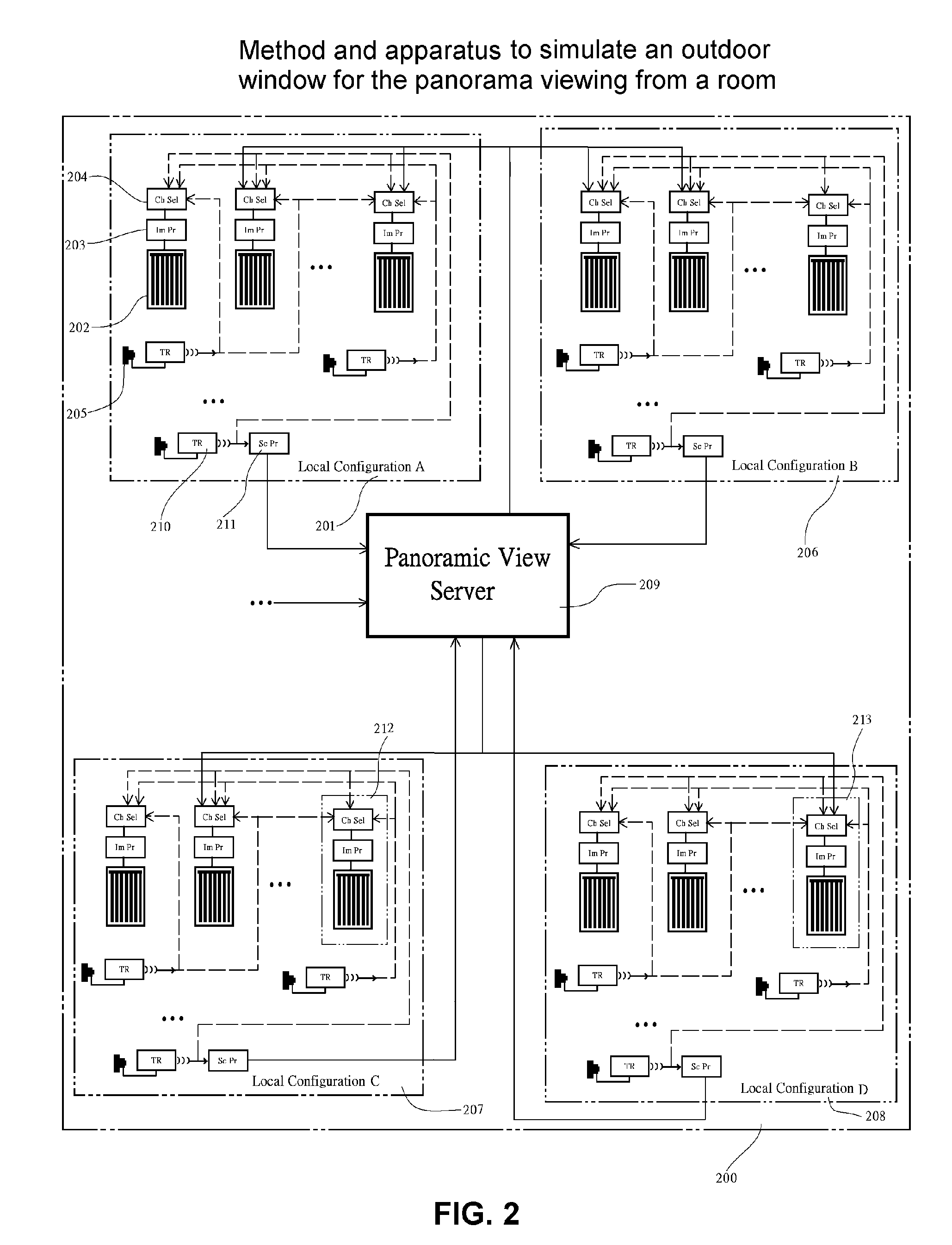
[0018]FIG. 1 shows a big building, a big hotel in particular, partitioned into many rooms. Some rooms, room 1 for example, have a window facing north direction and thus a north view is available. Similarly, room 2, room 3 and room 4 have west, south and east views respectively, while the inner room 5 has no view at all. Suppose that north view is a ocean view and is considered as the most desirable one among the four available views, this particular view is not only desirable for inner room 5, it is desirable for rooms 2, 3 and 4 as well, if there is a way to get it. Further more, if the elevation of the floor shown in FIG. 1 is not high enough, other buildings can still block the views from rooms facing north direction, thus an artificial outdoor window that can be used to dynamically display the good ocean view is still very desirable.

[0019] In FIG. 2, four of many possible configurations for the arrangement of the connections between cameras such as 205 and display monitors such...


PUM


Abstract

A method and system to bring panorama views for displaying in multiple rooms, especially windowless rooms are shown in present invention. The display unit installed in each room not only used as a display screen for quasi live panoramic views from all corners around the whole world, but also equipped with real window covering or controllable artificial window covering such that the unit itself looks and functions like a real outdoor visible window with window covering. While the version implemented with real window covering operated synchronously with operation of the display screen, the version implemented with artificial window covering offers more choices that the window covering on display is replaceable and can also be controlled like a real one. These apparatus not only can be used to display quasi real-time outdoor scene, but also can be used to display other video images and serves as a decoration item for a windowless room particularly in a hotel or panorama sensitive building wherein a good view is important.

Description

1. CROSS-REFERENCE INFORMATION [0001] The present application is an extension to the co-pending U.S. patent application Ser. No. 10 / 604709 filed on Aug. 12, 2003 entitled as “Method and apparatus to simulate an outdoor window for a windowless room”. The present application also claims the priority to co-pending U.S. Provision patent application Ser. No. 60 / 522176 entitled “Method and apparatus to simulate an outdoor window for panorama viewing from a room” filed on Aug. 27, 2004.2. FIELD OF THE INVENTION [0002] The present invention relates to the simulation of outdoor windows for displaying dynamic panorama from multiple desired locations along with real window coverings or manipulatable window covering images. It relates to the application of a surveillance system as well. 3. BACKGROUND [0003] Recent advances in display monitor technologies such as liquid crystal display (LCD), organic light emitting diode (OLED) and plasma displays have been obvious. It is easy to notice that the...

Claims


Application Information

Patent Timeline
Patent Type & Authority Applications(United States)
IPC IPC(8): H04N7/18
CPCG09F27/00G09F19/22
Inventor JONG, CHIOU-MUH
Owner JONG CHIOU MUH
Learn More